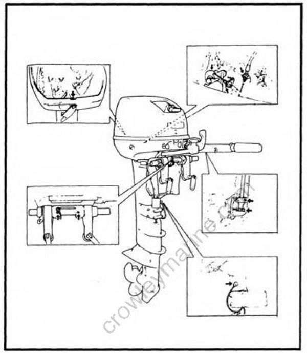
PERIODIC SERVICE
FUEL SYSTEM
Fuel line
- Inspect:
- Fuel line
Break/Leak/Damage → Replace.
- Fuel line
CONTROL SYSTEM
Ignition timing adjustment
- Check:
- Fully advanced ignition timing
Incorrect → Adjust.
- Fully advanced ignition timing
Checking steps:
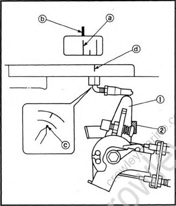
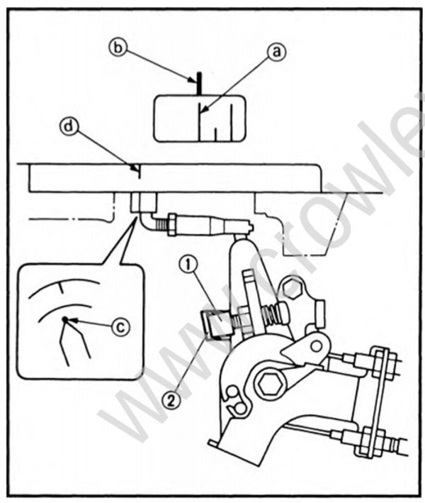
- Turn the flywheel clockwise so that its specified marking (a) aligns with the starter cover marking (b).
Fully advanced position: 30° BTDC
- Turn the magneto control lever (1) so that it contacts the fully advanced stopper (2).
- Check the timing indicator (c) so that it aligns with the marking (d) on the flywheel.
- Adjust:
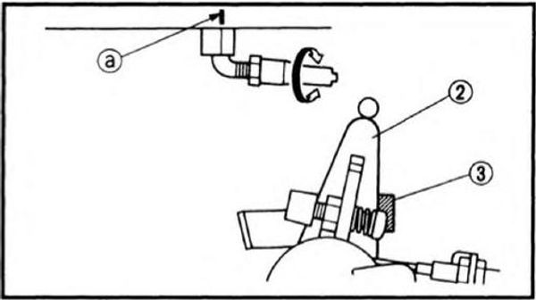
- Link joint
Adjustment steps:
- Loosen the lock nut (1).
- Disconnect the link joint from the magneto control lever.
- Remove the spark plug of No. 1 cylinder
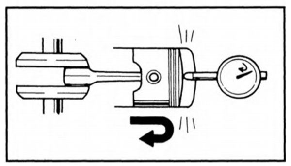
- Attach the dial gauge to the spark plug hole.
Dial gauge: YU-03097/90890-01252
Dial gauge stand: YU-01256
- Slowly turn the flywheel clockwise until the piston reaches top dead center (TDC).
- Set the dial gauge to zero at TDC.
- Turn the flywheel counterclockwise until the dial gauge indicates that the piston position is at a specified distance from TDC.
Piston position: 4.22 mm (0.166 in) BTDC
- Turn the magneto control lever (2) so that it contacts the fully advanced stopper (3).
- Adjust the link joint length so that the timing indicator aligns with the marking (a) on the flywheel.
- Tighten the lock nut.
- Check:
- Fully retard ignition timing
Incorrect → Adjust.
- Fully retard ignition timing
Checking steps:
- Turn the flywheel clockwise so that the its specified marking (a) aligns with the starter cover marking (b).
Fully retard position: 5° ATDC
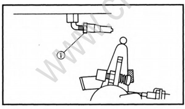
- Turn the magneto control lever so that the fully retard screw (1) contacts the fully retard stopper (b).
- Check the timing indicator (c) so that it aligns with the marking (d) on the flywheel.
- Adjust:
- Fully retard screw
Adjustment steps:
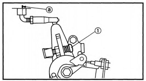
- Turn the flywheel clockwise until the dial gauge indicates that the piston position is at specified distance from TDC.
Piston position: 0.12 mm (0.005 in) ATDC
- Turn the magneto control lever so that the fully retard screw contacts the fully retard stopper.
- Adjust the fully retard screw (1) so that the timing indicator aligns with the marking (a) on the flywheel.
Throttle link adjustment
Before adjusting the throttle link, the ignition timing should be adjusted.
- Inspect:
- Fully closed position
Incorrect → Adjust.
- Fully closed position
Checking steps:
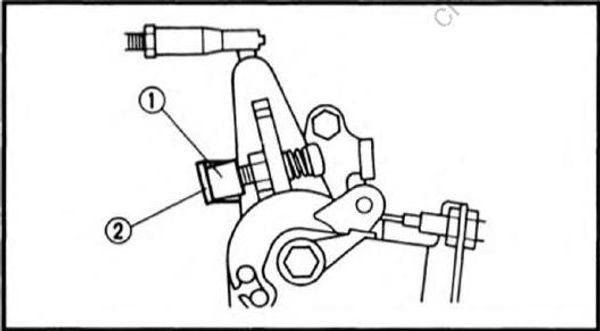
- Close the throttle grip fully.
- Check the fully retard screw (1) so that it contacts the fully retard stopper (2).
- Adjust:
- Throttle cable adjuster
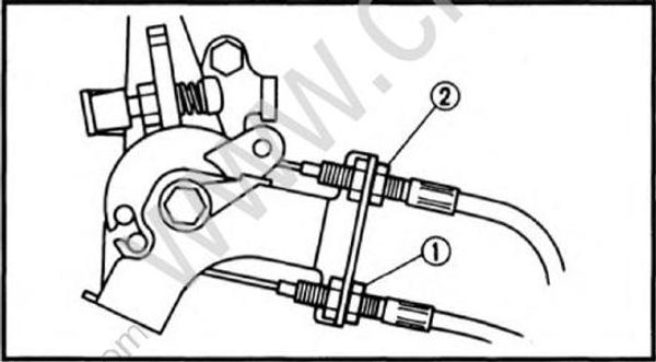
Adjustment steps:
- Loosen the lock nuts (1), (2).
- Turn the magneto control lever until the fully retard screw contacts the fully retard stopper.
- Adjust the throttle cable adjuster until there is specified free play between the stoppers of the pulley (3) and free acceleration lever (4).
Free play: 1 mm (0.04 in)
- Tighten the lock nut (1).
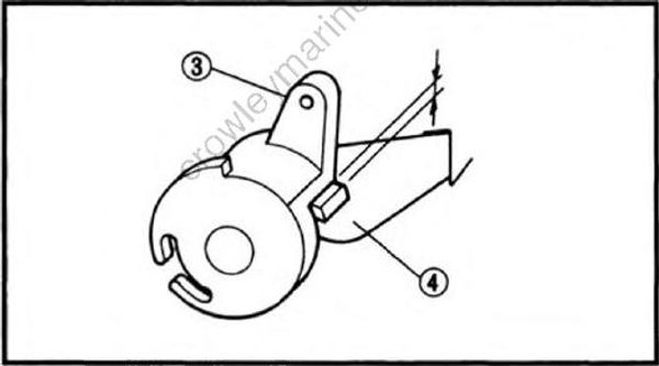
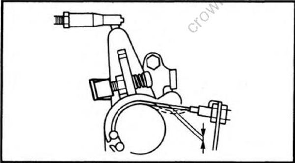
- Adjust the throttle cable adjuster until there is specified free play on the throttle cable.
Free play: 1 mm (0.04 in)
- Tighten the lock nut (2)
- Check:
- Throttle operation
Rough operation → Repair.
- Throttle operation
Start-in-gear protection adjustment
Check:
- Start-in-gear protection operation
Incorrect → Adjust.
- Start-in-gear protection operation
Adjust:
- Start-in-gear protection wire
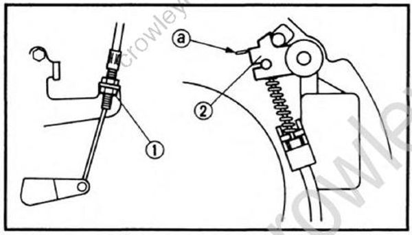
Adjustment steps:
- Set the shift lever in neutral.
- Loosen the lock nut (1).
- Adjust the start-in-gear protection wire adjuster so that the end of the stopper (2) aligns with the marking (a) of the starter case.
- Tighten the lock nut.
Idle speed adjustment
Before adjusting the idle speed, be sure to adjust the throttle link.
- Measure:
- Idle speed
Out of specification → Adjust.
- Idle speed
Idle speed: 750 ± 50 rpm
Measuring steps:
- Start the engine and allow it to warm up for a few minutes.
- Attach the tachometer to the high tension lead of the cylinder#!.
Tachometer: YU-08036-A/90890-06760
- Adjust:
- Idle speed
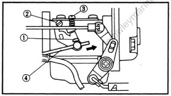
Adjustment steps:
- Loosen the screw (1) of the carburetor throttle lever.
- Turn in the pilot screw (2) until it is lightly seated.
- Turn out the pilot screw to specification.
Pilot screw (turns out): 1-1/2 ± 1/4
- Adjust the throttle stop screw (3) in or out until specified idle speed is obtained.
Turning in → Idle speed becomes higher.
Turning out → Idle speed becomes lower.
- Pull the acceleration rod (4) until the fully retard screw contacts the fully retard stopper.
- Tighten the screw (1).
Screw: 1 Nm (0.1 m•kg, 0.7 ft•lb)
LOWER UNIT
Gear oil
Check:
- Gear oil
Milky oil → Replace the oil seal.
Slag oil → Check the gear, bearing and dog.
- Gear oil
Check:
- Gear oil level
Oil level is low → Add oil to proper level.
- Gear oil level
Replace:
- Gear oil
Replacement steps:
- Tilt up the motor.
- Place a pan under the drain plug (1).
- Remove the drain plug, then the oil level plug ©and drain the oil thoroughly.
- Place the outboard motor in an upright position.
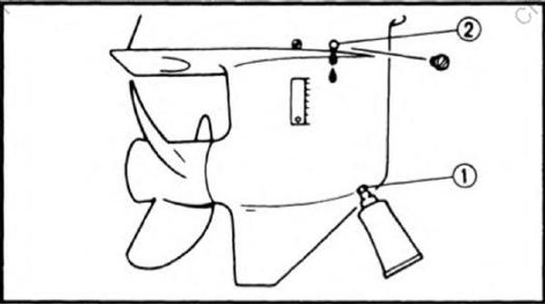
- Fill the gear oil through the drain hole until it overflows at the level hole.
Recommended oil: GEAR CASE LUBE (USA) or Hypoid gear oil, SAE # 90
Oil capacity: 250 cm³ (8.45 US oz, 8.80 lmp oz)
- Refit the oil level plug and then oil drain plug.
Lower unit leakage check
- Check:
- Pressure holding
Pressure falls → Inspect seals and component parts.
- Pressure holding
Checking steps:
- Attach the tester to the oil-level hole.
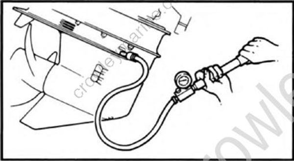
Pressure tester: YB-03595/90890-06762
- Apply the specified pressure.
Pressure: 100 kPa (1.0 kg/cm², 14.2 psi)
- Check that the pressure is held as specified for 10 seconds.
Do not over-pressurize. Excess pressure may cause the air to leak out.
GENERAL
Anode
- Inspect:
- Anode
Scale → Clean.
Oil/grease → Clean.
Wear/Excessively consumed → Replace.
- Anode
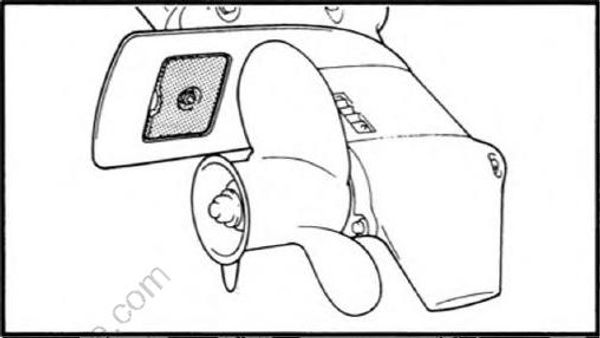
Do not oil, grease or paint the anode, or the function of the sacrificial anode will be spoiled.
Battery
Battery electrolyte is poisonous and dangerous, causing severe burns, etc. It contains sulfuric acid. Avoid contact with skin, eyes, or clothing.
Antidote:
EXTERNAL; Flush with water.
INTERNAL; Drink large quantities of water or milk. Follow with milk of magnesia, beaten egg, or vegetable oil. Call physician immediately.
EYES; Flush with water for 15 minutes and get prompt medical attention.
Batteries produce explosive gases: Keep sparks, flame, cigarettes, etc. away. Ventilate when charging or using in a closed space. Always wear eye protection when working near batteries.
KEEP OUT OF REACH OF CHILDREN.
● Batteries vary among manufacturers. Therefore the following procedures may not always apply. Consult your battery manufacturer's instructions.
● Disconnect the black negative lead first to prevent the risk of shorting.
- Inspect:
- Battery fluid level
- Battery fluid specific gravity
Spark plug
- Inspect:
- Electrode (1)
Wear/Damage → Replace. - Insulator color (2)
Distinctly different color → Check the engine condition.
- Electrode (1)
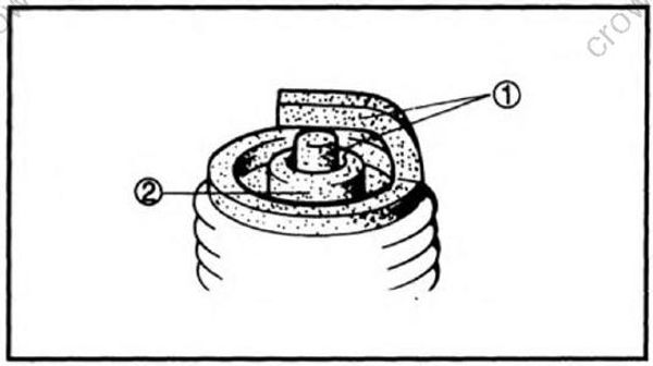
Color guide
Medium to light tan color: Normal
Whitish color:Lean fuel mixture
Plugged fuel mixture
Air leak
Wrong settings
Blackish color:Overly rich mixture
Electrical malfunction
Excess oil used
Defective spark plug
Clean:
- Spark plug
Clean the spark plug with a spark plug cleaner or wire brush.
- Spark plug
Measure:
- Spark plug gap (a)
Out of specification → Alter gap.
Use a wire gauge.
- Spark plug gap (a)
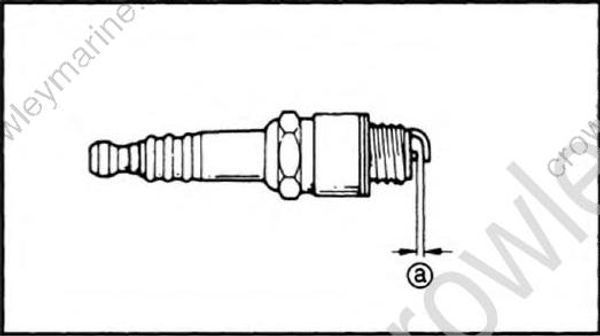
Spark plug gap: 0.9 ~ 1.0 mm (0.035 ~ 0.039 in)
- Tighten:
- Spark plug
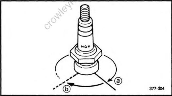
Spark plug: 25 Nm (2.5m•kg, 18 ft•lb)
● Before installing a spark plug, clean the gasket surface and plug surface. Also it is suggested to apply a thin film of Anti Seize Compound to the spark plug threads to prevent future thread seizure.
● If a torque wrench is not available, a good estimate of the correct torque is a further 1/4 to 1/2 turns (b) on finger tightened (a) spark plug.
Greasing point
- Apply:
- Water resistant grease