

Control System Selection
Outboard remote control systems provide the operator with tools for:
- Starting and stopping the engine
- Shifting into Forward, Neutral, or Reverse
- Changing engine speed
- Changing the tilt/trim angle of the outboard.
The remote control system must include the following features:
- Shift stroke must be 1.125 to 1.330 in. (28.6 to 33.8 mm) between Neutral and Forward
- Throttle stroke must PUSH for open
- Start-in-gear prevention
- Emergency stop switch with lanyard-multiple-outboard installations require separate start switches and a single emergency stop switch
- Connections for engine monitor warning system Refer to Engine Monitor System on p. 11.
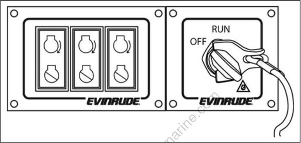
ICON style multiple start switches with master power/emergency stop switch
The remote control used must have start-in-gear prevention. This feature can prevent injuries resulting from unexpected boat movement when the outboard starts.
Always install and recommend use of an emergency stop/key switch. Doing so will reduce the risk of personal injury or death should the operator fall away from the controls or out of the boat.
Several remote control options, including both mechanical and electronic systems, are available in the Evinrude/Johnson Genuine Parts and Accessories catalog.
Mechanical control systems use push/pull cables to physically move the shift and throttle components on the outboard.
These systems use a Modular Wiring System (MWS) harness to carry start, stop, and trim signals (analog) to the outboard. Specific harness selection depends on the type of Information Display system being used. Refer to INFORMATION DISPLAY SYSTEMS on p. 11.
Electronic control systems, such as Evinrude ICON, manage all engine control functions through a low-voltage, digital data network.
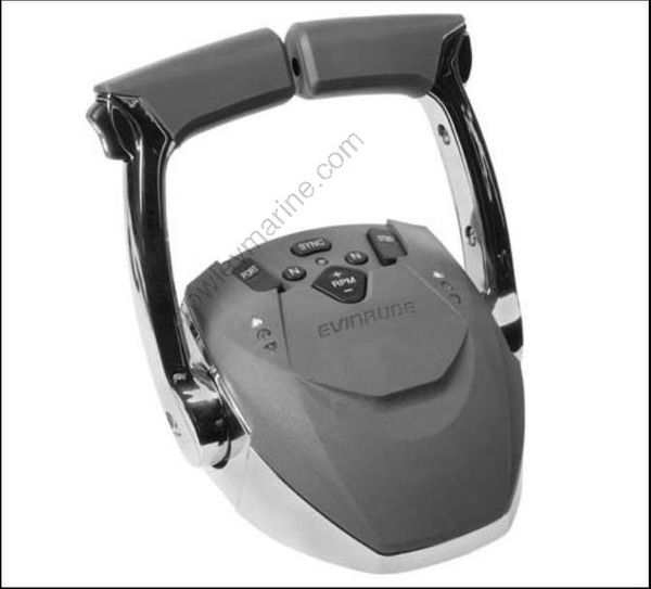
Evinrude ICON multi-engine control
These systems can only be used with outboards equipped for electronic control, including Evinrude ETEC models identified with a “DE” prefix in the model number.
Conversion kits are available to add electronic control capabilities to standard ETEC models from 150 to 300 HP, 2008 and newer.
Control Installation
Plan the installation of remote controls carefully, following all instructions provided with the control.
Select an appropriate location based on the boat configuration.
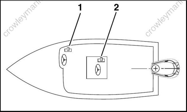
- Side console
- Center console
IMPORTANT: The mounting location must be a flat surface and must be strong enough to provide rigid support. Strengthen mounting surface as necessary.
Place remote control at proposed location and check clearance around remote control lever at full throttle in FORWARD and then at full throttle in REVERSE. There must be at least 2.5 in. (64 mm) of clearance between the handle and any part of the boat throughout the control lever travel.
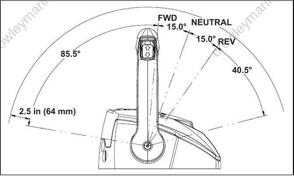
Typical control clearances
Use an appropriate drill template to cut mounting holes. Templates are included with the control instructions.
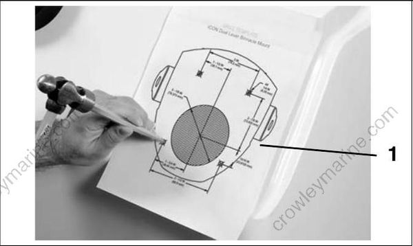
- Template
Install control with hardware provided.
IMPORTANT: Make sure remote control assembly is secure and does not move during operation.
Control Cable Routing
Control cables and harnesses should be routed along a protected path to the rear of the boat and secured to prevent movement or damage.
Harness connections should be mounted in a dry location, away from bilge and motor well areas.
Control cables should be long enough to allow a 12 in. (30 cm) cable loop at the front of the outboard when the cables are routed from the side of the splash well.
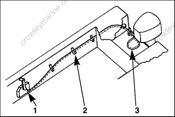
- Surface side-mount remote control
- Cable support
- 12 in. (30 cm) cable loop at front of outboard
Evinrude ICON Networks
All control information is transferred between the outboard and an Evinrude ICON system through a single network cable. For complete installation instructions, refer to the Evinrude ICON Remote Control System Installation Guide, P/N 764952.
When installing an ICON network, remember:
• Control network must include two cable hubs
• DO NOT use the key switch to power accessories (switched B+)—use an ICON Accessory Power Relay Kit
• The ICON Gateway provides a connection for an I-Command Information Display network.
Refer to Evinrude ICON / I-Command Harness Connections on p. 14 for a typical network installation diagram.
