

Shimming workflow
• Make sure to drain the gear oil before measuring the backlash.
• If the backlash is within specification, shimming is not required.
• When assembling the original inner parts and a new lower case, shimming is required.
• When replacing the pinion, forward gear, reverse gear, bearings, drive shaft, or propeller shaft housing, shimming is required.
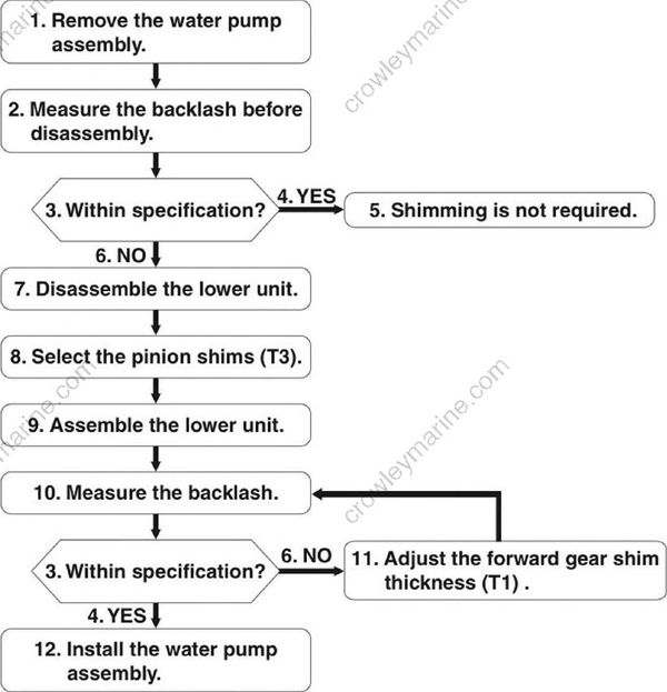
- Remove the water pump assembly.
- Measure the backlash before disassembly.
- Within specification?
- YES
- Shimming is not required.
- NO
- Disassemble the lower unit.
- Select the pinion shims (T3).
- Assemble the lower unit.
- Measure the backlash.
- Adjust the forward gear shim thickness (T1).
- Install the water pump assembly.
Shimming check sheet
Lower case deviation
Pinion height (mm)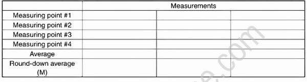
Forward gear backlash (mm)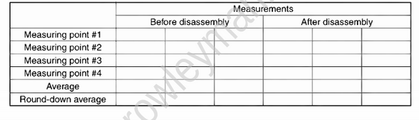
Reverse gear backlash (mm)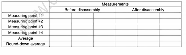
Forward gear shim (T1) thickness adjustment in 2 places (mm)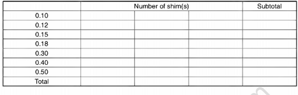
Reverse gear shim (T2) thickness adjustment in 2 places (mm)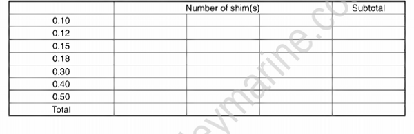
Measuring the forward gear backlash before disassembly
Install the lower unit onto a repair stand.
Remove the water pump assembly. See “Removing the water pump and shift rod” (8-42).
Set the gear shift to the N position.
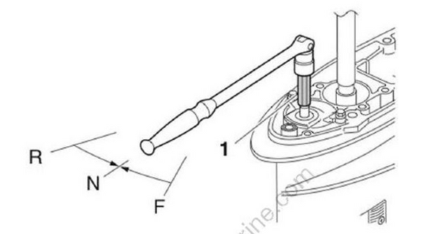
Shift rod push arm "1" : YB-06681
- Set up the special service tools “1” and “2”, and then tighten the center bolt “4” temporarily.
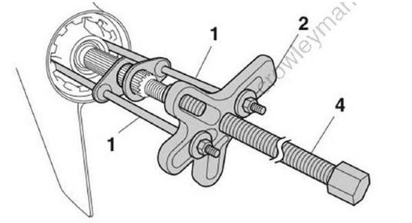
Bearing housing puller "1" : YB-06207
Universal puller "2" : YB-06117
Turn the lower unit so that the propeller shaft is pointing down.
Turn the drive shaft 10 times or more to seat the taper roller bearing.
While holding the drive shaft to prevent it from turning, tighten the center bolt “1” to the specified torque.
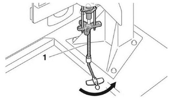
Center bolt "1" (shimming) : 5 Nm (0.5 kgf•m, 3.7 ft•lb)
Turn the lower unit to its upright position.
Install the special service tool “1” onto the drive shaft at the lowest possible position where the shaft diameter is 18.0 mm (0.71 in).
Install the handle stopper “2” so that it rests on the step at the position “a” on the drive shaft, and then tighten the nuts “3” temporarily.

Backlash indicator rod “1” : YB-06265
Handle stopper “2” : EU0-23814-30 *1
*1. Order from Yamaha Parts warehouse.
- Set up the special service tools “1”, “2”, and “3”, and then place another special service tool “4” on the handle stopper “5” to apply a load.
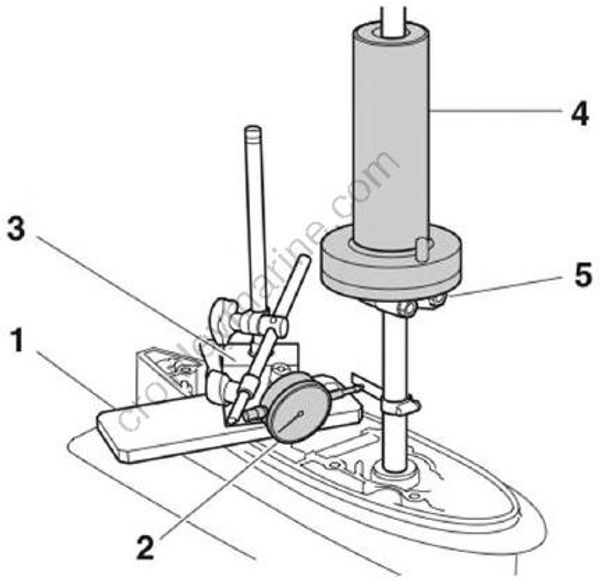
Backlash adjustment plate “1” : YB-07003
Dial indicator gauge “2” : YU-03097
Magnetic base stand “3” : YU-A8438
Pinion height gauge “4” : YB-06669
- Turn the drive shaft slowly clockwise and counterclockwise, and then measure the backlash between where the drive shaft stops in each direction.
• Do not turn the drive shaft using too much force. Otherwise, the forward gear will turn, leading to incorrect measurements.
• When turning the drive shaft, hold it using a little force. A knocking sound may be heard when the drive shaft is turned, but this is the sound of the pinion contacting the reverse gear and does not affect the backlash measurement.
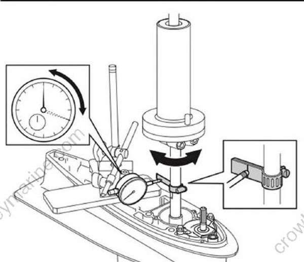
- Turn the drive shaft 180° clockwise and measure the backlash again.
• Measure the backlash at 4 points: “a”, “b”, “c”, and “d”, turning the drive shaft 180° clockwise after each measurement.
• Write down the measurement data in the shimming check sheet.
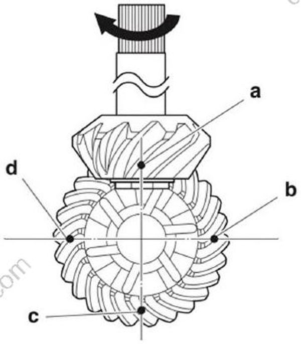
- Determine the backlash average, and then round down the average to the 1/100 place.
Example:
(mm)
| Measurement point “d” | 0.30 |
| Measurement point “e” | 0.36 |
| Measurement point “f” | 0.34 |
| Measurement point “g” | 0.33 |
| Average | 0.3325 |
| Round-down average | 0.33 |
- Check that the forward gear backlash average is within specification.
Adjust the shim thicknesses if the forward gear backlash is out of specification.
Forward gear backlash : 0.09-0.71 mm (0.0035-0.0280 in)
- Remove the special service tools, and then install the oil seal housing and water pump assembly. See “Installing the water pump" (8-21).
Shimming
- Before selecting the forward gear shim (T1), make sure to select the pinion shims (T3).
- When assembling the lower unit to measure the backlash after selecting the pinion shims (T3), do not apply gear oil, grease, or sealant to the parts.
- When assembling the lower unit after shimming is completed, make sure to apply gear oil, grease, and sealant to the specified areas.
Shim location

Selecting the pinion shim (T3)
- Spray anti-rust lubricant on the bearing before installation. Do not apply gear oil to the parts. Otherwise, correct measurements cannot be obtained.
- Keep the parts free of foreign material, such as dirt and lint.
Be careful not to damage the measurement plane surface of the special service tool. Otherwise, correct measurements cannot be obtained.
Disassemble the lower unit.
Install the taper roller bearing “1” and drive shaft between “a” and “b” of the special service tool “2”, and then tighten the pinion height gauge bolts “c” temporarily.
Do not install the pinion shim (T3).

Pinion height gauge "2" : YB-06669
- Install the pinion “1” and pinion nut “2”, and then tighten the pinion nut “2” temporarily.
When tightening the pinion nut, make sure that the drive shaft turns smoothly.
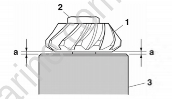
- Check that there is a gap “a” between the pinion “1” and the special service tool “3”.
If there is no gap and the drive shaft does not rotate, the special service tool could be damaged.
If there is no gap, the pinion shim (T3) may not have been removed.
Install the special service tool “1” to the drive shaft spline, and hold the special service tool “1”.
Tighten the pinion nut “2” to the specified torque.
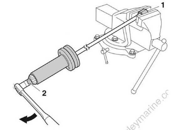
Drive shaft holder 4 "1" : YB-06049
Pinion nut "2" : 94 Nm (9.4 kgf•m, 69.3 ft•lb)
Place the pinion so that it is facing up, and hold it in the upright position.
Turn the drive shaft 10 turns or more to seat the taper roller bearing.
Tighten the pinion height gauge bolts “2” to the specified torques in 4 stages so that the distance “b” between the upper part and the lower part of the special service tools “1” become equal.
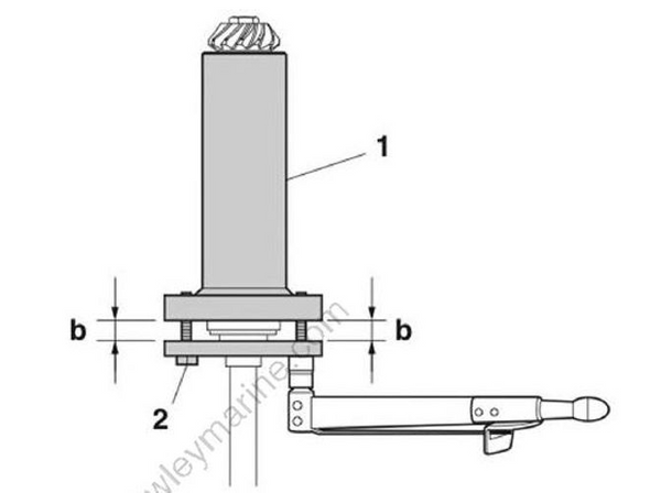
Pinion height gauge bolt "2" :
Ist : 1 Nm (0.1 kgf•m, 0.7 ft•lb)
2nd : 2 Nm (0.2 kgf•m, 1.5 ft•lb)
3rd : 3 Nm (0.3 kgf•m, 2.2 ft•lb)
4th : 4 Nm (0.4 kgf•m, 3.0 ft•lb)
- Recheck the gap “a” between the pinion “1” and the special service tool “2”.
If there is no gap, the shim(s) (T3) may not have been removed.
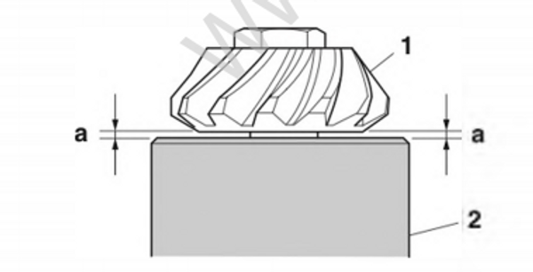
- Measure the distance between the pinion “1” and the special service tool “2”.
• When measuring the distance, insert the end of the thickness gauge straight into the gap at the measurement point. Do not insert the thickness gauge at an angle.
• Measure the distance at 4 points: “a”, “b”, “c”, and “d”.
• Write down the measurement data in the shimming check sheet.
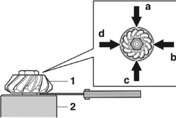
- Determine the distance average, and then round down the average to the 1/100 place.
Example:
(mm)
| Measurement point “a” | 0.20 |
| Measurement point “b” | 0.20 |
| Measurement point “c” | 0.19 |
| Measurement point “d” | 0.18 |
| Average | 0.1925 |
| Round-down average (M) | 0.19 |
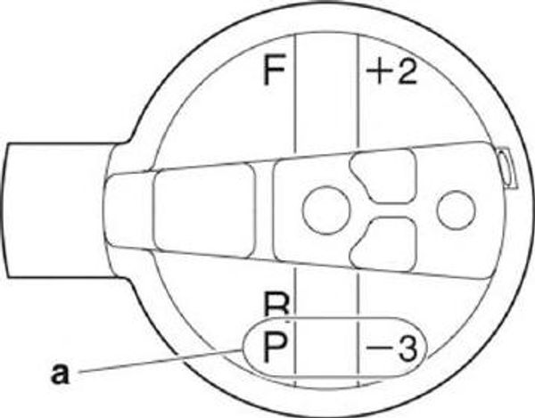
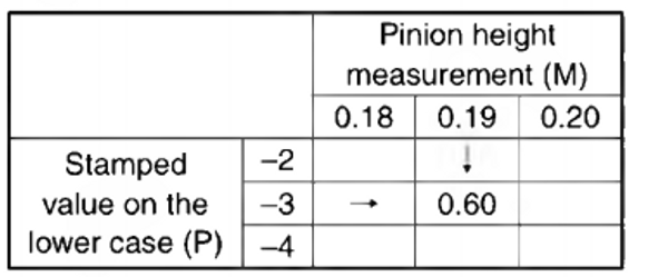
- Determine the pinion shim (T3) thickness adjustment using the “Pinion shim (T3) selection table” according to the rounded average (M) and the deviation (P) stamped on the lower case. See “Pinion shim (T3) selection table” (A-11).
The (P) mark “a” is stamped on the trim tab mounting surface of the lower case in 0.01 mm units. If the (P) mark is unreadable, replace the lower case.
Available shim thicknesses : 0.10, 0.12, 0.15, 0.18, 0.30, 0.40, 0.50 mm
Example:
(M) = 0.19
(P) = -3
(T3) = 0.60 mm from the “pinion shim (T3) selection table”
- Remove the special service tools, and then install the determined pinion shims (T3).
Measuring the forward gear backlash
- Spray anti-rust lubricant on the gears and bearings before installation. Do not apply gear oil to the parts. Otherwise, correct measurements cannot be obtained.
- Keep the parts free of foreign material, such as dirt and lint.
- When measuring the forward gear backlash, use the original bearings and shims.
- Install the original forward gear shims (T1).
• If the original forward gear shims (T1) are missing, install new shims with a combined thickness of 0.50 mm.
• Do not reuse a shim if deformed or scratched.
Install the taper roller bearing outer race. See steps 2 and 3 in “Assembling the lower case” (8-54).
Install the forward gear assembly, drive shaft, pinion, and pinion nut. See steps 1-3 in “Installing the drive shaft” (8-56).
Check that the drive shaft turns smoothly.
Install the propeller shaft housing assembly. See “Installing the propeller shaft housing assembly” (8-57).
Check that the drive shaft turns smoothly.
Measure the forward gear backlash. See steps 3-15 in “Measuring the forward gear backlash before disassembly” (8-64).
Forward gear backlash : 0.09-0.71 mm (0.0035-0.0280 in)
Adjusting the forward gear shim thickness (T1)
Remove the taper roller bearing outer race. See step 1 in “Disassembling the lower case” (8-52).
Measure the thickness of original forward gear shim (T1) in 2 places.
Do not reuse a shim if deformed or scratched.
- Determine the forward gear shim (T1) thickness adjustment using the “Forward gear shim (T1) selection chart” according to the backlash measurement (BL1) from “Measuring the forward gear backlash”. See “Forward gear shim (T1) selection chart (F50B, F60B)” (A-12).
• If the shim thickness adjustment value is positive, increase the current shim thickness by that amount and, if the value is negative, decrease the current shim thickness by that amount.
• The gray-colored area on the selection chart indicates the range of the specified backlash. Shimming is not required if the measured backlash is within the gray-colored area.
• The values for the shim thickness adjustments specified in the selection chart are intended to obtain the median value within the range for the specified forward gear backlash.
• The table that follows the selection chart shows the shim thickness adjustments for the points marked on the chart.
Example:
Backlash measurement (BL1) = 0.05 mm “a” Forward gear shim (T1) thickness adjustment = -0.19 mm “b”
The current shim thickness must be decreased by 0.19 mm.
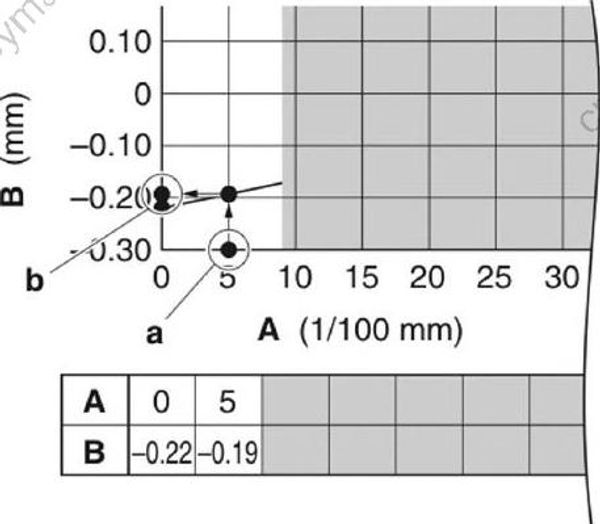
A Backlash measurement (BL1)
B Shim thickness adjustment
- Calculate the new forward gear shim (T1) thickness.
• Use the lowest number of shims to obtain the required shim thickness.
• If the calculated shim thickness cannot be obtained with a combination of the available shims, decrease the shim thickness by 0.01 mm.
Calculation formula:
New forward gear shim (T1) thickness = Current forward gear shim thickness + shim thickness adjustment
Example:
Use the following formula when the shim thickness adjustment value is positive.
Current forward gear shim thickness = 0.50 mm
Shim thickness adjustment = 0.21 mm
New forward gear shim (T1) thickness = 0.50 mm + 0.21 mm = 0.71 mm
Use the following formula when the shim thickness adjustment value is negative.
Current forward gear shim thickness = 0.50 mm
Shim thickness adjustment = -0.19 mm
New forward gear shim (T1) thickness = 0.50 mm + (-0.19 mm) = 0.31 mm
Available shim thicknesses : 0.10, 0.12, 0.15, 0.18, 0.30, 0.40, 0.50 mm
- Install the determined forward gear shims (T1) and taper roller bearing outer race.
