

Step 1: Newly developed V6 4-stroke engine
The F225 is a newly developed 60-degree V6 4-stroke engine with a very compact and lightweight design. Its size and weight are almost the same as the V6 2-stroke engines that are in current use. This F225 offers numerous advantages of a 4-stroke engine. Compared to conventional 2-stroke models, it emits much cleaner exhaust gases, offers a better fuel economy, and realizes lower noise levels at idle and full throttle.
Through the newly developed “In-bank exhaust system,” which discharges exhaust gases from the center of both banks, the engine block and the surrounding equipment have been made compact. In addition, the six independent intake passages help to achieve a high level of driveability and power output.
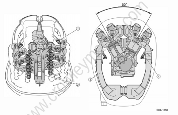
S69J1250
(1) Electronic Fuel Injection
(2) In-bank exhaust system
(3) Pulse tuned long intake tracks
(4) Individual inside track fuel injectors
Step 2: Crankcase
The crankcase is made of cast aluminum, however steel has been cast into the areas for the crank shaft bearings. By distinguishing the area that requires strength from the area that allows the use of a lighter material, both weight reduction and a stronger construction have been achieved.
The caps for the crankshaft bearings are secured with four bolts to ensure a high level of assembled rigidity.
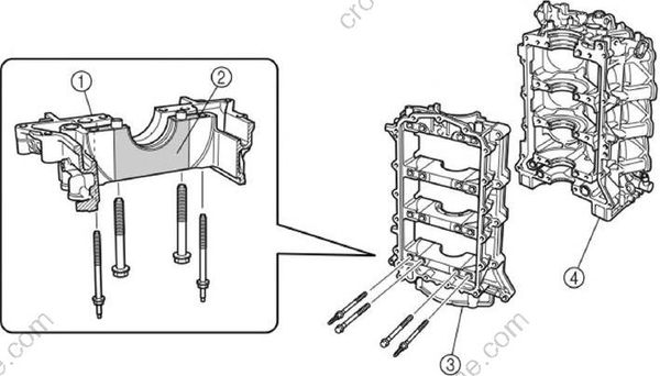
S69J1260
(1) Casted aluminum
(2) Steel
(3) Crankcase
(4) Cylinder block
Step 3: Crankshaft
The crankshaft has been forged to realize a high-strength and high-rigidity construction. In the 60 degree V6 cylinder configuration, the crankshaft pins are staggered 60 degrees from each other.
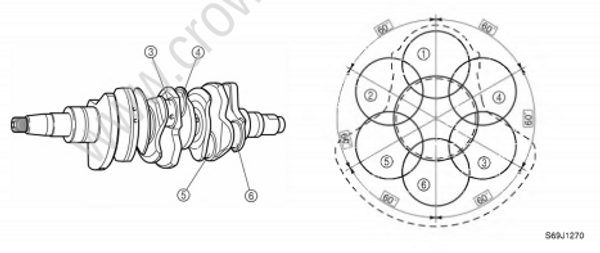
S69J1270
(1) Crankpin #1
(2) Crankpin #2
(3) Crankpin #3
(4) Crankpin #4
(5) Crankpin #5
(6) Crankpin #6
Step 4: Piston
The piston has been carved out of a forged stock. To prevent the valves from coming in contact with the piston, the piston is provided with a valve recess. If the engine goes out of timing and a valve opens when the piston is at top-dead-center, this recess prevents the valve from coming in contact with the piston, thus preventing engine damage.
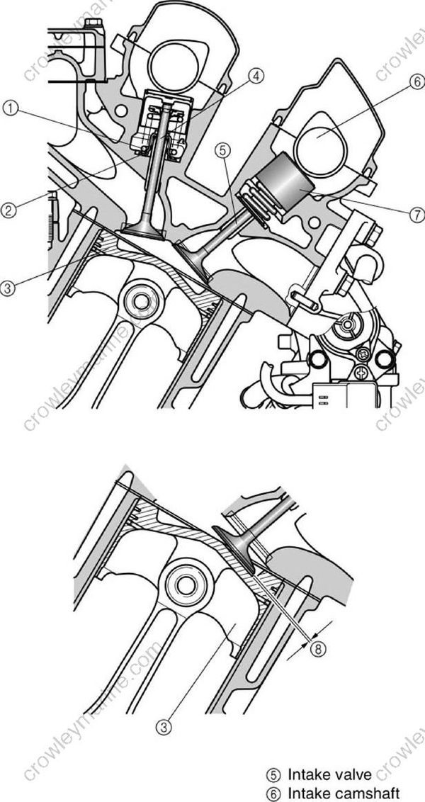
S69J1280
(1) Valve spring
(2) Valve seal
(3) Piston
(4) Valve stem
(5) Intake valve
(6) Intake camshaft
(7) Intake lifter
(8) Valve recess
Step 5: Valve train system
The valve train consists of a total of four camshafts, with two in each bank.
The camshafts are driven with the combination of a belt and chains. The crankshaft turns the belt to drive the exhaust camshafts in both banks. Chains connect the exhaust camshafts to the intake camshafts in the cylinder heads to drive the intake camshafts.
In addition, the timing belt offers quieter operation, and the cam chains help to achieve a compact configuration through the use of individual driven sprockets.
Timing belt
The timing belt, which is driven by the drive sprocket that is attached to the crankshaft, rotates the driven sprockets that are attached to the exhaust camshafts of both banks.The drive sprocket for the timing belt is secured to the crankshaft by four bolts, and it can be removed easily for servicing.In addition, the material of the driven sprockets has been changed from the previous metal to plastic for weight reduction.
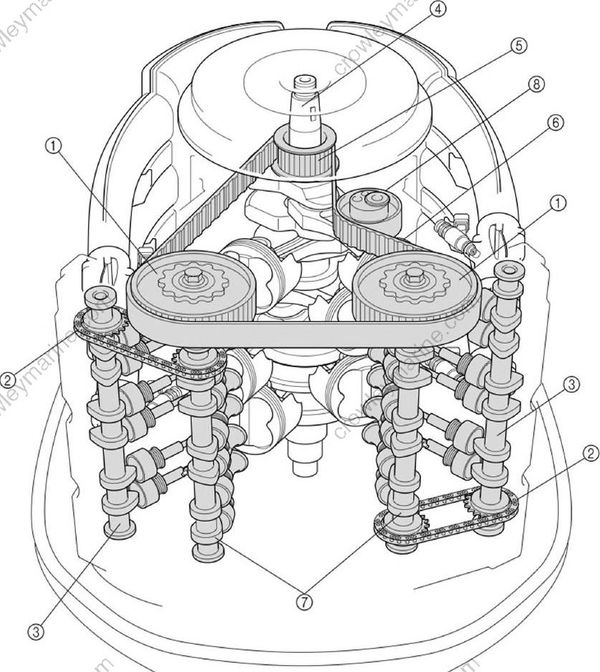
S69J1290
(1) Driven sprocket
(2) Timing chain
(3) Intake camshaft
(4) Crankshaft
(5) Drive sprocket
(6) Timing belt
(7) Exhaust camshaft
(8) Hydraulic timing belt tensioner
Tensioner
A timing chain tensioner is provided at the mid-span of the timing chain, between both camshafts. The timing chain tensioner uses the force of a spring to maintain its tension. After the engine is started, oil is pumped into the tensioner, and the resulting pressure causes the tension to increase. A total of three tensioners are used, one for the timing belt, and one for each timing chain of both banks, to maintain proper tension and to ensure the reliability of the valve train.
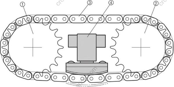
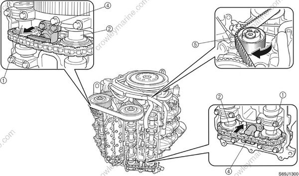
S69J1300
(1) Intake camshaft
(2) Exhaust camshaft
(3) Timing chain
(4) Timing chain tensioner
(5) Hydraulic timing belt tensioner
Step 6: Intake system
Throttle valve
A total of six intake throttle valves are provided, one for each cylinder. Together with the intake silencer that offers enhanced intake efficiency and the injectors that are provided at each throttle body, the throttle valves help to improve the intake efficiency of the engine. As a result, this engine produces a higher power output and realizes better driveability.
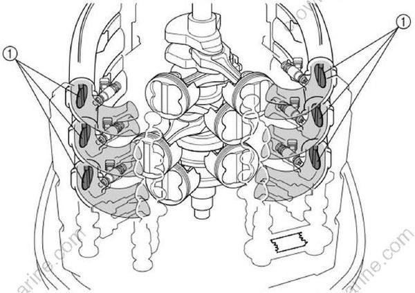
S69J1310
(1) Throttle valve
Step 7: Exhaust system
In-bank exhaust system
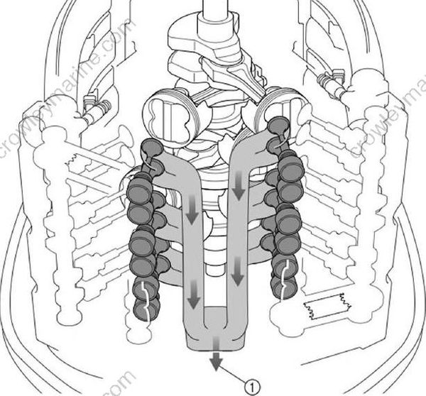
The exhaust passage of the F225 is located in the V bank, a layout that is the opposite of conventional V6 engines. By providing the exhaust passage in the V bank, the engine has been made considerably more compact.
S69J1320
(1) Exhaust gas
Exhaust passage during idle
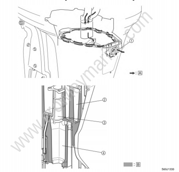
To reduce noise when the engine is idling, the exhaust gas passage of the F225 has adopted a labyrinth construction. During idling, the exhaust gas passes through the passage on the side of the exhaust guide, and enters the upper case through a hole in the upper case gasket. When it fills the upper case, the exhaust gas enters another passage on the side of the exhaust guide through another hole in the upper case gasket. Then, it is discharged through the idle port that is provided in the upper case.
The exhaust manifold and muffler in the upper case are surrounded by the water jackets to reduce exhaust noise. The water jackets also help prevent corrosion by preventing the exterior of the exhaust manifold and muffler from coming in direct contact with the exhaust gas.
S69J1330
(1) Idle port
(2) Oil pan
(3) Exhaust manifold
(4) Muffler
[A] Exhaust gas
[B] Water
Step 8: Fuel system
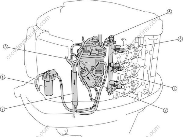
The fuel flows in the following order: fuel filter, low-pressure fuel pump, vapor separator, high-pres sure fuel pump, and injectors. The excess fuel at the injectors passes through the pressure regulator and fuel cooler, and returns to the vapor separator.
When the engine start switch is turned on, the injectors of all cylinders operate before the pump relay is actuated to prevent the injectors from sticking.
S69J1340
(1) Fuel filter
(2) Low-pressure fuel pump
(3) Vapor separator
(4) High-pressure fuel pump
(5) Fuel injector
(6) Pressure regulator
(7) Fuel cooler
Low-pressure fuel pump
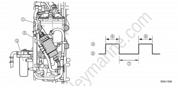
The F225 has adopted a newly developed, low-pressure electrical fuel pump, in place of the low pressure mechanical fuel pump used in the previous electronic fuel injection system. With the adoption of the electric pump, the routing of the fuel system has been made more compact. To prevent the over-pumping of fuel, this pump operates for 10 seconds, and stops for 20 seconds when the engine is operating at low speeds.
The pump operates constantly if the engine speed is 1,200 r/min or higher, or for several seconds (which vary by ambient temperature) after the engine is started. At other times, it operates for 10 seconds, and stops for 20 seconds to prevent over-pumping.
S69J1350
(1) Vapor separator
(2) Low-pressure fuel pump
(3) Fuel filter
(4) On
(5) Off
(6) 10 seconds
(7) 20 seconds
Step 9: Electronic control system
The ECM controls the ignition timing, the fuel injection timing, the fuel injection volume, and the ISC and it maintains a stoichiometric air-fuel ratio in all operating conditions, including starting and idling. Also, the ECM converts the signals from the input sensors and sends instructions to each part.
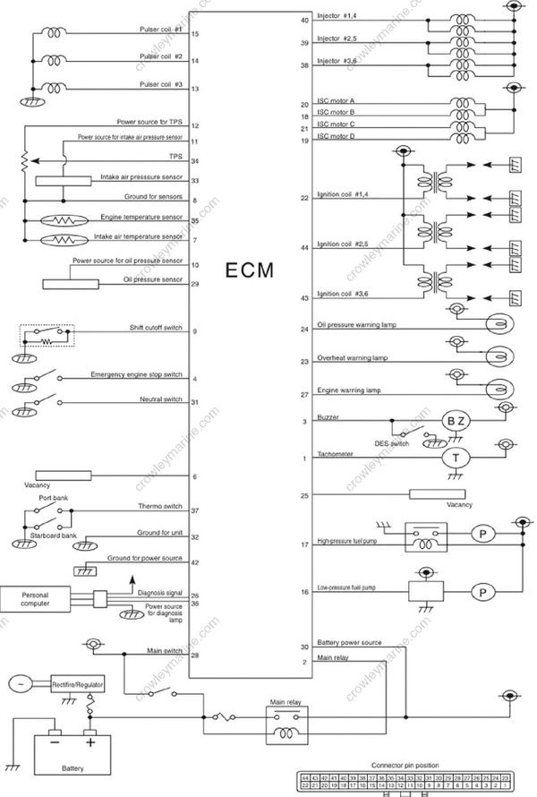
S60L1180
Ignition and fuel injection timing
This engine adopted the group injection system that the fuel required for one combustion is injected twice per one cycle.
Therefore, the injector driving circuits can be integrated to 3 circuits and a simpler electrical structure is obtained.
Firing order : #1, #2, #3, #4, #5, #6
Injection order : #1 and #4 ➝ #2 and #5 ➝ #3 and #6 (group injection)
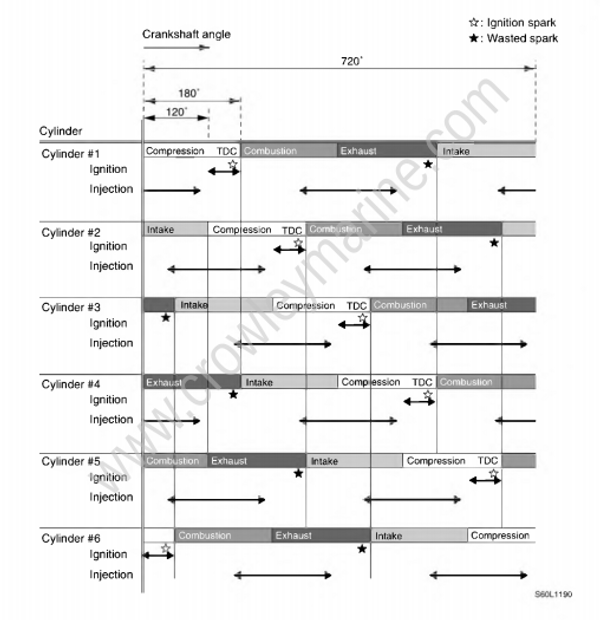
S60L1190
Step 10: PTT (Power trim and tilt) unit
The PTT unit has been newly developed for the F225. Based on the field-proven 61A type, its PTT fluid passage and internal valve construction have been changed for this application. Although the valves of the 61A type have been distributed to the various areas of the gear pump housing, the valves of the new PTT unit have been concentrated in the vicinity of the gear pump to improve their serviceability. In addition, the material of the gear pump housing has been changed to enhance its corrosion resistance.
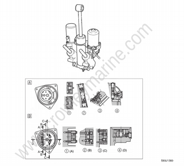
S69J1380
(1) Gear pump
(2) Main valve
(3) Relief valve
(4) Manual valve
[A] 61A type
[B] F225 type
