

Throttle link rod
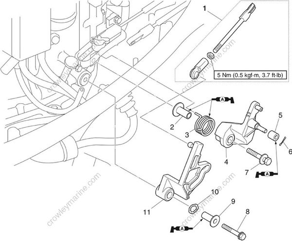
| No | Part name | Q’ty | Remarks |
|---|---|---|---|
| 1 | Throttle link rod | 1 | |
| 2 | Collar | 1 | |
| 3 | Spring | 1 | |
| 4 | Throttle control lever | 1 | |
| 5 | Throttle cam roller | 1 | |
| 6 | Cotter pin | 1 | Not reusable |
| 7 | Bolt | 1 | M6 x 35 mm |
| 8 | Bolt | 1 | M6 x 45 mm |
| 9 | Collar | 1 | |
| 10 | Wave washe | 1 | |
| 11 | Throttle cam | 1 |
Removing the throttle link
Remove the clip “1 ” and throttle cable “2”.
Remove the throttle link rod “3”.
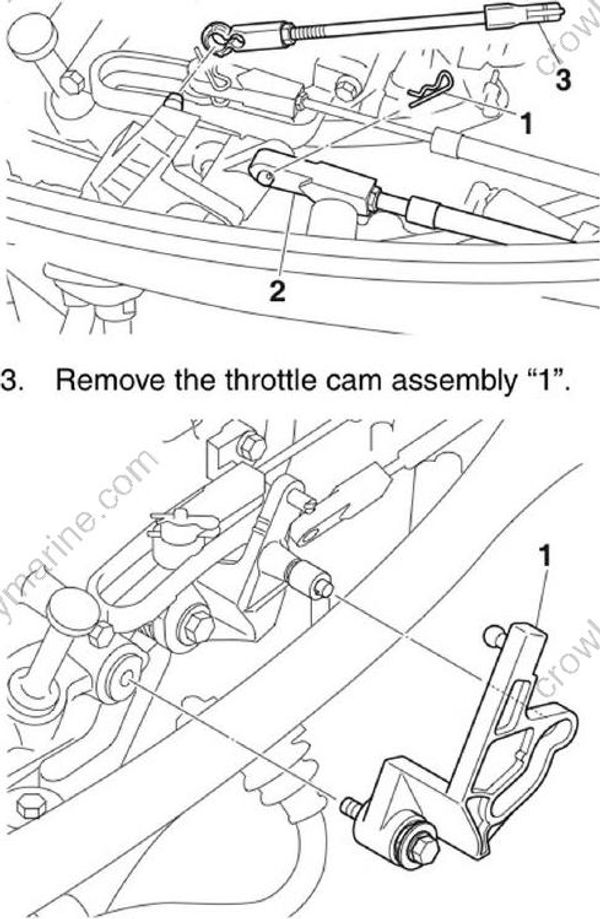
- Remove the throttle cam assembly "1"
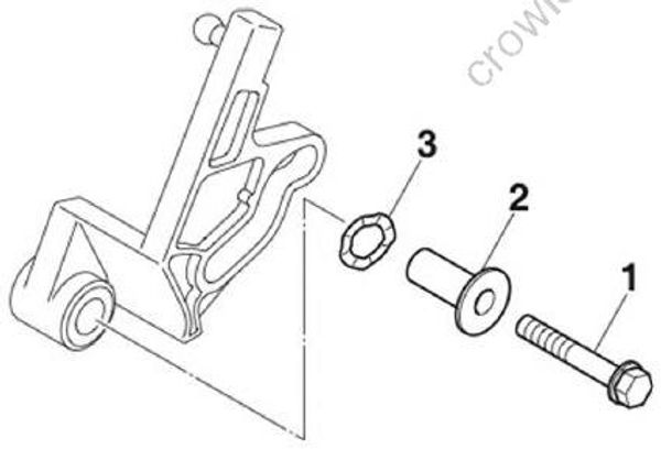
- Remove the bolt “1”, collar “2”, and wave washer “3”.
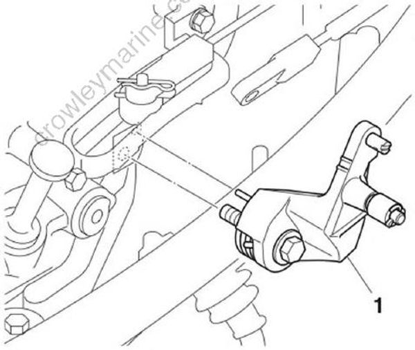
- Remove the throttle control lever assembly “1”
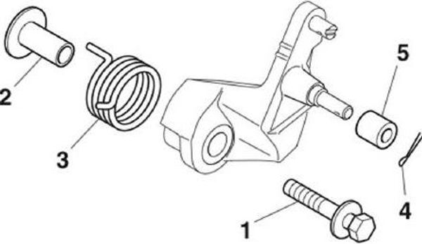
- Remove the bolt “1”, collar “2”, spring “3”,cotter pin “4”, and roller “5”.
Installing the throttle link
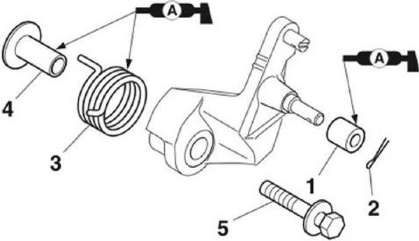
- Install the roller “1”, a new cotter pin “2”,the spring “3”, the collar “4”, and the bolt“5”.
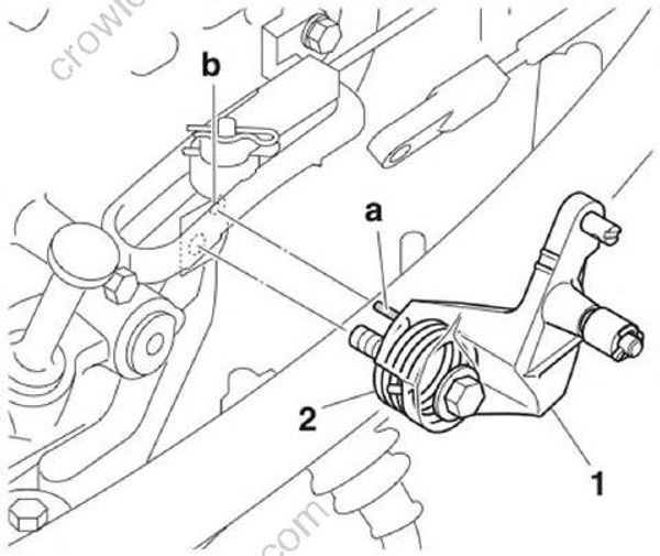
- Install the throttle lever assembly “1” to the crankcase. Fit the end “a” of the spring “2” into the hole “b” in the crank case.
- Install the and bolt “3”.
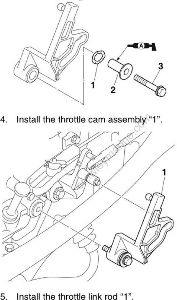
Install the throttle cam assembly "1".
Install the throttle link rod "1".
Install the throttle cable “2” and clip “3”.See “Installing the shift cable and throttle cable” (3-12).
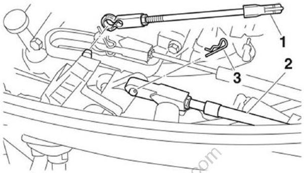
- Adjust the throttle link rod. See “Adjusting the throttle link rod” (6-30).
Adjusting the throttle link rod
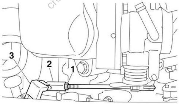
- Loosen the link rod locknut “1”, and then remove the throttle link rod “2” from the throttle cam “3”.
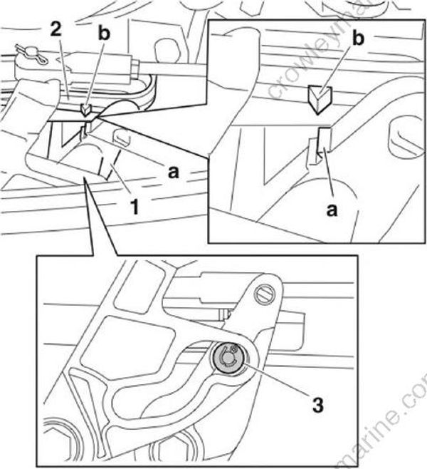
Check that the protrusion “a” on the throttle lever “1” and the protrusion “b” on the shift bracket “2” are aligned.
Turn the throttle cam until it contacts the roller “3” slightly.
- Adjust the throttle link rod length so that its end “a” fits onto the protrusion “b” on the throttle cam, and then install the throttle link rod to the throttle cam.
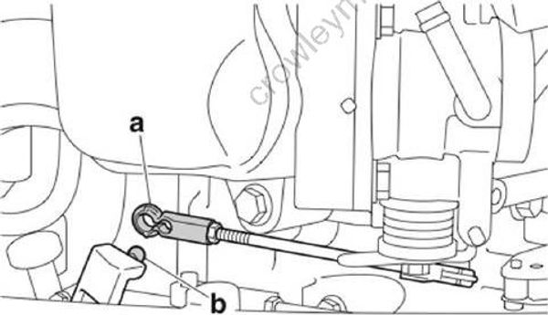
- Tighten the link rod locknut “1” to the specified torque.
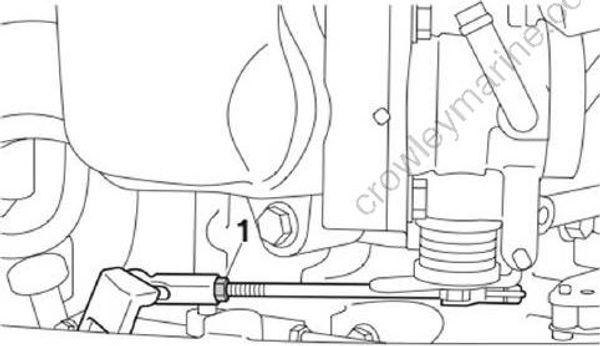
Link rod locknut “1”: 5 Nm (0.5 kgf-m, 3.7 ft lb)
