

Evinrude® E-TEC® G2 74° V6 Warranty Powerhead Service Kits
SAFETY INFORMATION
The following symbols and/or signal words may be used in this document:
Indicates a hazardous situation which, if not avoided, will result in death or serious injury.
Indicates a hazardous situation which, if not avoided, could result in death or serious injury.
Indicates a hazardous situation which, if not avoided, could result in minor or moderate personal injury.
Indicates an instruction which, if not followed, could severely damage engine components or other property.
These safety alert signal words mean:
ATTENTION!
BECOME ALERT!
YOUR SAFETY IS INVOLVED!
For safety reasons, this kit must be installed by an authorized Evinrude dealer. This instruction sheet is not a substitute for work experience. Additional helpful information may be found in other service literature.
DO NOT perform any work until you have read and understood these instructions completely.
Torque wrench tightening specifications must strictly be adhered to.
Should removal of any locking fastener (lock tabs, locknuts, or patch screws) be required, always replace with a new one.
When replacement parts are required, use Evinrude/Johnson® Genuine Parts or parts with equivalent characteristics, including type, strength and material. Use of substandard parts could result in injury or product malfunction.
Always wear EYE PROTECTION AND APPROPRIATE GLOVES when using power tools.
Unless otherwise specified, engine must be OFF (not running) when performing this work.
Always be aware of parts that can move, such as flywheels, propellers, etc.
Some components may be HOT. Always wait for engine to cool down before performing work.
If you use procedures or service tools that are not recommended in this instruction sheet, YOU ALONE must decide if your actions might injure people or damage the outboard.
This instruction sheet may be translated into other languages. In the event of any discrepancy, the English version shall prevail.
TO THE INSTALLER: Give this sheet and the operating instructions to the owner. Advise the owner of any special operation or maintenance information contained in the instructions.
TO THE OWNER: Save these instructions in your owner’s kit. This sheet contains information important for the use and maintenance of your engine.
Use these kits on Evinrude E-TEC G2 74° V6 outboards.
Kit Components
| Part Number | Description | Quantity |
|---|---|---|
| – | Warranty Powerhead | 1 |
| 5009481 | O-Ring Kit | 1 |
| 320107 | Tie Strap | 6 |
| 346150 | 18.5 mm Clamp | 1 |
| 346786 | 15.7 mm Clamp | 2 |
| 348838 | 10.5 mm Clamp | 3 |
| 348839 | 17.0 mm Clamp | 1 |
| 351685 | 34.6 mm Clamp | 1 |
| 353156 | 22.6 mm Clamp | 1 |
| 356360 | 56.0 mm Clamp | 1 |
| 357516 | 51.5 mm Clamp | 1 |
Powerhead Removal
Protect against hazardous fuel spray. Before starting any fuel system service, carefully relieve fuel system pressure. Refer to Relieving Fuel System Pressure in the correct service manual.
To prevent accidental starting while servicing, twist and remove spark plug leads.
Removal
IMPORTANT: Before removing the powerhead trim the engine to the vertical position.

Engine in Vertical Position
Remove the top engine cover. Then remove the 4 inch plug from the center frame. Next remove the 3.5 inch plug from the air duct and the thread protector from the flywheel threads.
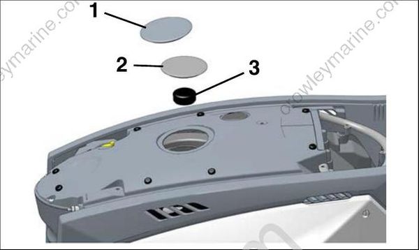
- 4 inch plug
- 3.5 inch plug
- Thread protector
Remove the front cover. Then disconnect all cables, buss cables and hoses from the engine.
Remove the rear cover, starboard and port frames and front frame. Refer to Engine Cover and Frame Service.
Remove the rigging grommets from the powerhead.
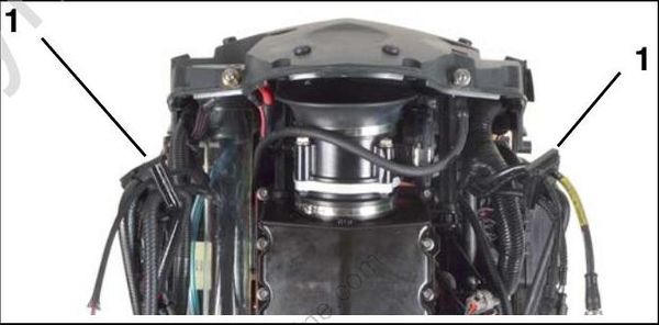
- Rigging grommets
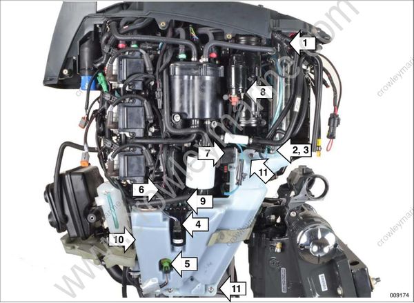
Starboard
Remove the following hose clamps and hoses:
51.5 mm clamp – Oil fill hose (upper), remove the hose from the center (top) frame.
10.5 mm clamp – Oil tank vent hose, remove the hose from the oil tank.
14.5 mm clamp – Remote oil fill hose, remove the hose from the oil tank.
Disconnect the electrical connectors from the following:
Crankcase oil pump (oil tank).
Low oil switch (oil tank).
Oil level sender (oil tank).
Trim relay, three Amp connectors and two 2 ring terminals (1 ground on the block and 1 on the starter solenoid).
Starter solenoid (small ring terminal).
Remove the 6 oil supply hoses from the crankcase oil pump.
Remove the following:
10.The trim relay from the oil tank.
11.The three nuts and washers retaining the oil tank. Then remove the oil tank
Port
Remove the following hose clamps and hoses:
15.7 mm Tee fitting, hose from tee fitting to DPS module, remove the hose from the tee fitting.
15.7 mm Hose, DPS module to adapter, remove the hose from the adapter fitting.
34.6 mm Y-fitting hose to adapter, remove the hose from the Y-fitting.
21.0 mm Tee fitting/thermostat hose to adapter, remove the hose from adapter fitting.
Tie strap Exhaust back pressure hose, remove the hose from adapter fitting.
Disconnect the electrical connectors from the following:
Exhaust temperature sensor
Shift actuator
DPS module
Remove the following:
- The three nuts and washers retaining the DPS module. Then remove the DPS module and cooling hoses as an assembly.

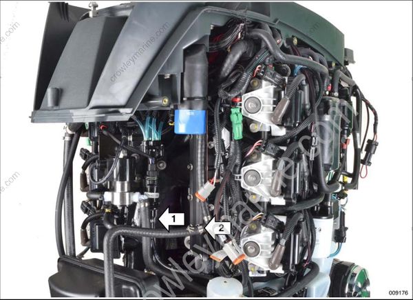
Rear
Remove the following hose clamps and hoses:
10.5 mm Rear oil pump(s) hose(s), remove the supply hose from the oil pump
15.7 mm Tee fitting, hose to overboard indicator, remove hose from tee fitting.
Lifting the Powerhead
To avoid personal injury, make sure the lifting capacity of the hoist is at least twice the weight of the outboard.
DO NOT allow the lift hook or chain from the hoist to come in contact with any part of the engine during lifting.
Use Lifting Fixture, P/N 357667, to lift the powerhead from the adapter. Use the centerline lifting eye to lift the complete engine. Use the off-set lifting eye to remove and install the powerhead, or to support the engine and remove and install the stern and swivel bracket assembly.
IMPORTANT: Carefully thread the lifting fixture into the threads of the flywheel at least 6 complete turns. Do NOT cross-thread the threads of the lifting fixture into the threads of the flywheel.
Install the lifting fixture completely into the flywheel. If needed, turn the flywheel until the lifting rings of the fixture are aligned front to back as
shown.
Make sure the off-set lifting eye is to the REAR of the engine. Fasten appropriate chain hook to the off-set lifting eye.
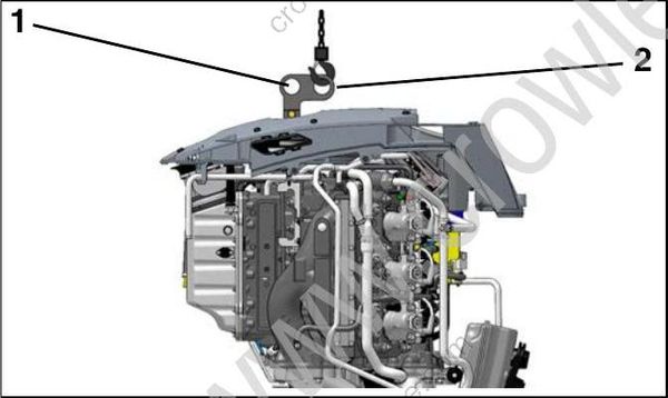
- Centerline lifting eye
- Off-set lifting eye (to REAR of engine)
Remove the 12 nuts and washers retaining the powerhead to the exhaust adapter and exhaust housing.
On the port side, there are four nuts and washers on the exhaust adapter and four nuts and washers on the exhaust housing.
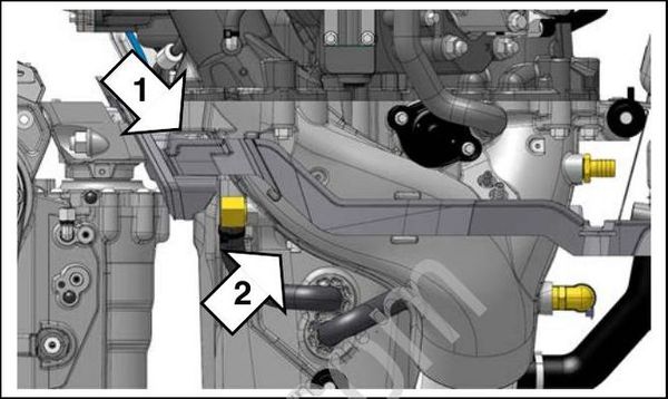
Port
- Four nuts and washers on the exhaust adapter
- Four nuts and washers on the exhaust housing
On the starboard side, there are four nuts and washers on the exhaust housing.

Starboard
- Four nuts and washers on the exhaust housing
Carefully lift the powerhead from the exhaust adapter. The powerhead should lift easily. If the powerhead does not lift easily, check for any fasteners or hose connections that may have been overlooked during the removal procedures.
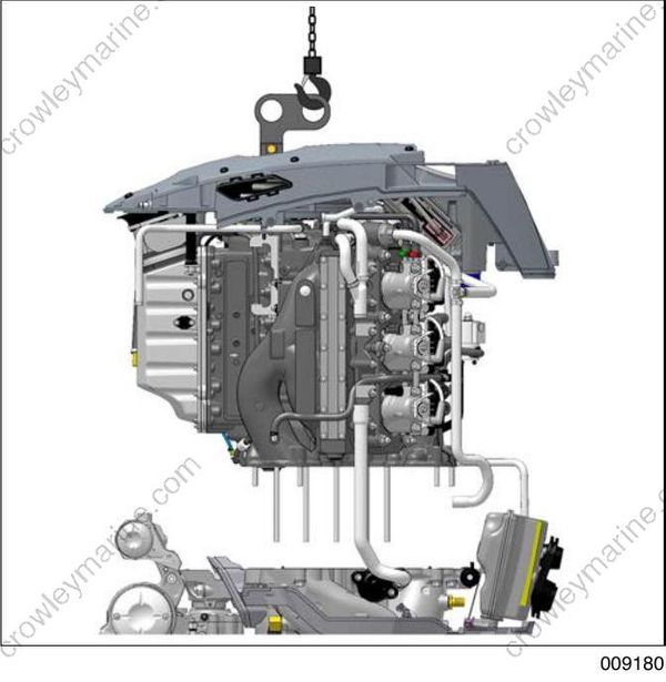
Remove the old o-rings from the exhaust adapter.
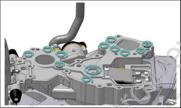
O-Rings
Clean the adapter with solvent.
Powerhead Installation
Install the 12 new o-rings onto the exhaust adapter.
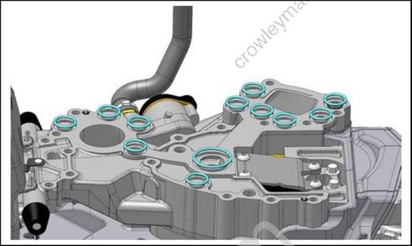
O-Rings
Remove the replacement powerhead from the shipping container.
To avoid personal injury, make sure the lifting capacity of the hoist is at least twice the weight of the outboard.
DO NOT allow the lift hook or chain from the hoist to come in contact with any part of the engine during lifting.
Use Lifting Fixture, P/N 357667, to lift the powerhead. Use the off-set lifting eye to lift the powerhead.
IMPORTANT: Carefully thread the lifting fixture into the threads of the flywheel at least 6 complete turns. Do NOT cross-thread the threads of the lifting fixture into the threads of the flywheel.
Install the lifting fixture completely into the flywheel. If needed, turn the flywheel until the lifting rings of the fixture are aligned front to back as shown.
Make sure the off-set lifting eye is to the REAR of the engine. Fasten appropriate chain hook to the off-set lifting eye.
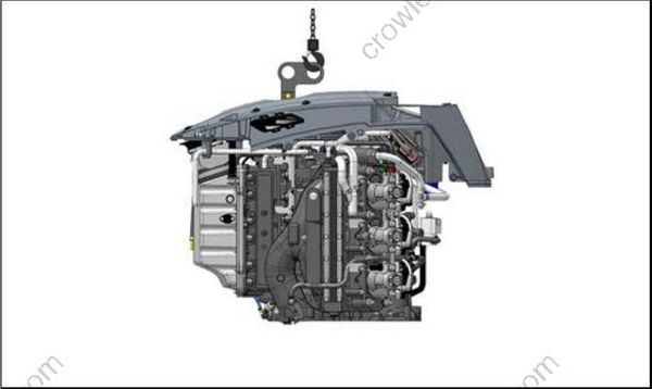
O-Rings
Install eight studs – M10 x 170 mm, P/N 357906, and four studs – M10 x 60 mm, P/N 357905, in the locations shown:
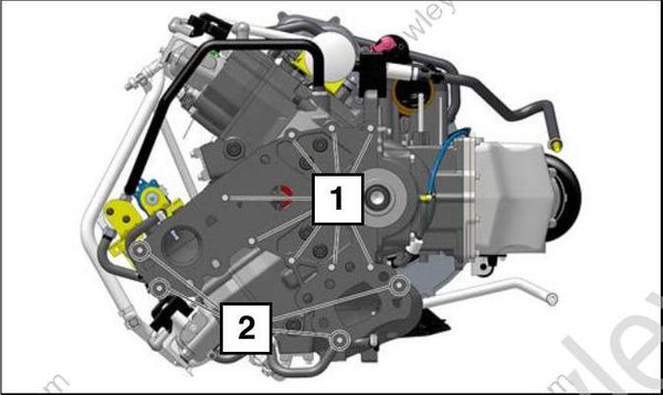
Stud Locations
- M10 x 170 mm, P/N 357906
- M10 x 60 mm, P/N 357905
Install studs into block to dimensions shown:

Stud Installation
- M10 x 170 mm, 145.25 mm (5.72 in.)
- M10 x 60 mm, 38.25 mm (1.5 in.)
Apply a 1/4 in. (6 mm) bead of high-temperature RTV, such as Permatex #26BR around the exhaust passage areas.
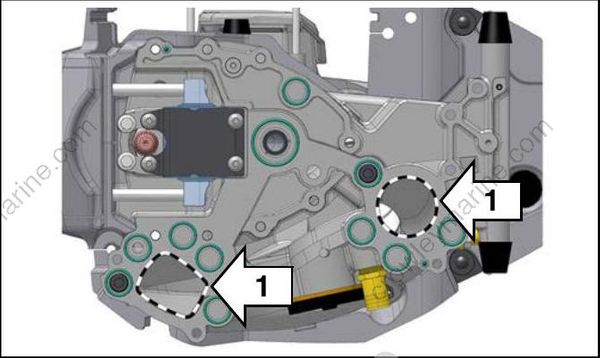
- Apply high-temperature RTV
Slowly lower the powerhead into position. Carefully guide the mounting studs of the powerhead into the exhaust adapter and exhaust housing.

O-Rings
Install the 12 washers and nuts to retain the powerhead to the exhaust adapter and exhaust housing.
On the port side, there are four washers and nuts on the exhaust adapter and four washers and nuts on the exhaust housing.
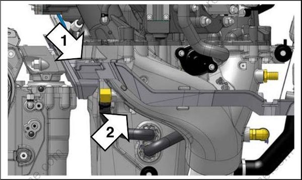
Port
- Four nuts and washers on the exhaust adapter
- Four nuts and washers on the exhaust housing
On the starboard side, there are four washers and nuts on the exhaust housing.

Starboard
- Four nuts and washers on the exhaust housing
Tighten the nuts in the sequence shown to a torque of 22 to 24 ft. lbs. (30 to 32 N·m).

Torque Sequence
Wait 5 minutes, then re-tighten the nuts. Use the same sequence and tighten to a torque of 22 to 24 ft. lbs. (30 to 32 N·m).
Remove the lift ring from the powerhead.
Rear
Install the following hoses and hose clamps:
Install the supply hose to the oil pump, secure with a new 10.5 mm Oetiker clamp.
Install the overboard indicator to the tee fitting, secure with a new 15.7 mm Oetiker clamp.
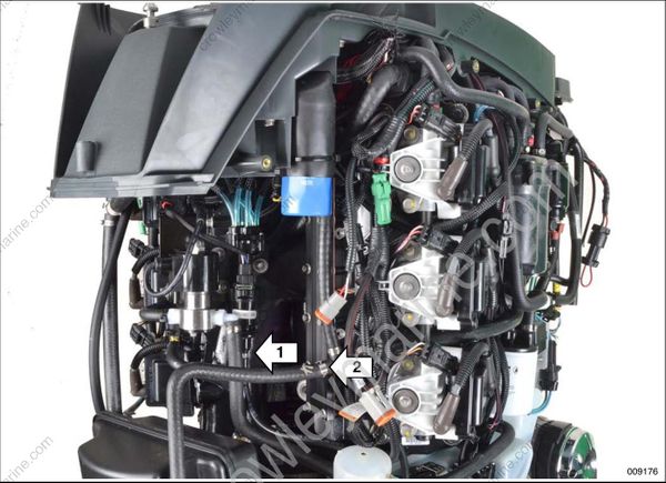
Port
Install the following:
- The DPS module and cooling hose assembly.
Install the following hoses and hose clamps:
The DPS module cooling hose to the tee fitting, secure with a new 15.7 mm Oetiker clamp.
The exhaust cooling hose (DPS module to exhaust adapter) to the adapter fitting, secure with a new 15.7 mm Oetiker clamp.
The Y-fitting to the exhaust adapter hose, secure with a new 34.6 mm Oetiker clamp.
The thermostat hose to the exhaust adapter fitting, secure with a new 21.0 mm Oetiker clamp.
The exhaust back pressure hose to the exhaust adapter fitting, secure with a new tie strap.
Connect the electrical connectors to the following:
Exhaust temperature sensor
Shift actuator
DPS module
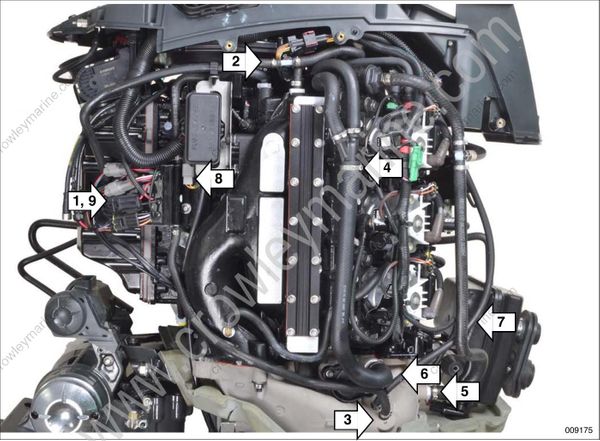
Starboard
Install the following:
The oil tank. Install the three washers and retaining nuts on the oil tank. Tighten the nuts to a torque of 15 to 17 ft. lbs. (20 to 23 N·m).
The trim relay on the oil tank.
The 6 oil supply hoses from the crankcase to the oil pump.
Install the following hoses and hose clamps:
The oil fill hose on to the center (top) frame, secure with a new 51.5 mm Oetiker clamp.
The oil tank vent hose on to the oil tank, secure with a new 10.5 mm Oetiker clamp.
The remote oil fill hose on to the oil tank, secure with a new 14.5 mm Oetiker clamp.
Connect the electrical connectors to the following:
Crankcase oil pump (oil tank).
Low oil switch (oil tank).
Oil level sender (oil tank).
10.Trim relay, three Amp connectors and two 2 ring terminals (1 ground on the block and 1 on the starter solenoid).
11.Starter solenoid (small ring terminal).

Install the rigging grommets on the powerhead hoses and buss cables.
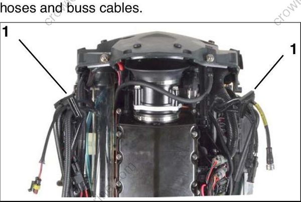
- Rigging grommets
Install plugs as indicated. Plugs MUST be installed to prevent water entry and/or engine performance issues.
Make sure plugs are securely installed to prevent loosening during engine operation.
Apply Triple Guard grease to the threads of the flywheel, then install the thread protector into the flywheel threads. Next install the 3.5 inch plug into the air duct and install the 4 inch plug into the center frame last.
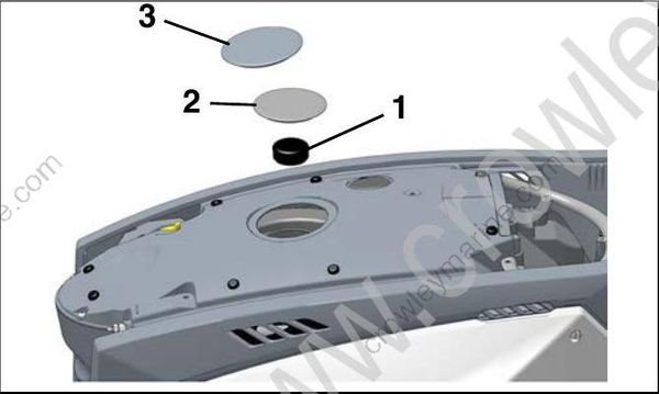
- Thread protector
- 3.5 inch plug
- 4 inch plug
Insert the grommets into the front frame, then install the front frame.
Install the port and starboard frames.
Install the rear covers Connect all cables, buss cables and hoses from the engine.Then install the front cover.
Refer to Engine Cover and Frame Service.