

Starter motor
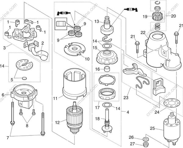
| No. | Part name | Q’ty | Remarks |
|---|---|---|---|
| 1 | Brush spring | 4 | |
| 2 | Brush assembly | 1 | |
| 3 | Brush holder assembly | 1 | |
| 4 | Starting motor gear assembly | 1 | |
| 5 | Washer set | 1 | |
| 6 | Bracket | 1 | |
| 7 | Bolt | 2 | M6 x 117 mm |
| 8 | Screw | 2 | M4 x 15 mm |
| 9 | Planetary gear | 3 | |
| 10 | Plate | 1 | |
| 11 | Stator | 1 | |
| 12 | Armature | 1 | |
| 13 | Clutch assembly | 1 | |
| 14 | Washer set | 1 | |
| 15 | Bracket | 1 | |
| 16 | Bearing | 1 | |
| 17 | Outer gear | 1 |

| No. | Part name | Q’ty | Remarks |
|---|---|---|---|
| 18 | Pinion shaft | 1 | |
| 19 | Pinion | 1 | |
| 20 | Pinion stopper set | 1 | |
| 21 | Bolt | 2 | M6 x 35 mm |
| 22 | Cover | 1 | |
| 23 | Lever assembly | 1 | |
| 24 | Seal set | 1 | Not reusable |
| 25 | Magnet switch | 1 | |
| 26 | Washer | 1 | |
| 27 | Nut | 1 | M8 |
Removing the starter motor
NOTICE
Before removing the starter motor, make sure to disconnect the negative battery terminal.
- Remove the starter motor from the power unit. See “Removing the starter motor” (7-24).
Checking the starter motor pinion
Check the pinion teeth. Replace the pinion if cracked or worn.
Turn the pinion counterclockwise to check that it operates smoothly and turn it clockwise to check that it locks in place.
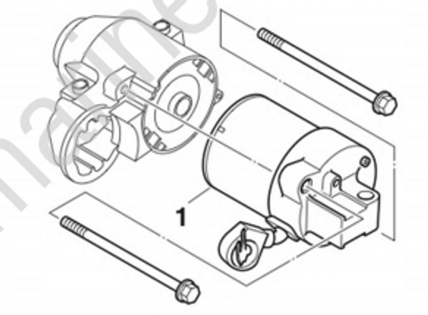
Disassembling the starter motor
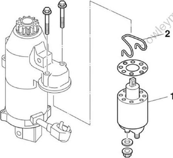
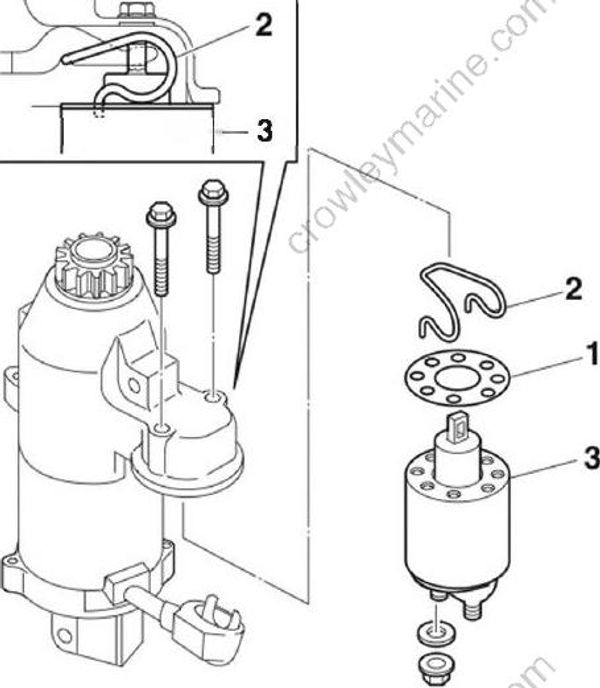
- Remove the magnet switch “1” and spring “2”.
- Push the pinion stopper “1” down, and then remove the clip “2”.
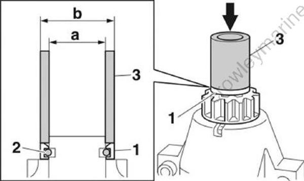
Pipe “3”: (commercially available)
“a”: 21.0 mm (0.83 in)
“b”: 26.0 mm (1.02 in)
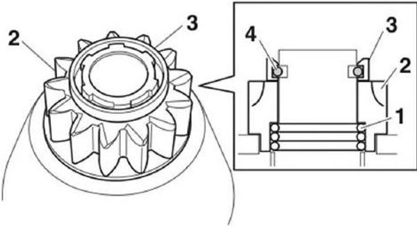
- Remove the pinion stopper “1”, pinion “2”, and spring “3”.
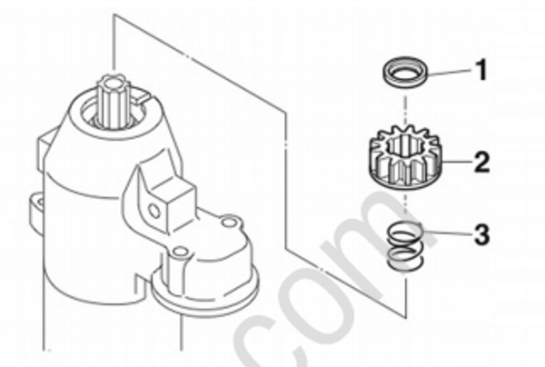
- Remove the pinion stopper "1", pinion "2", and spring "3".
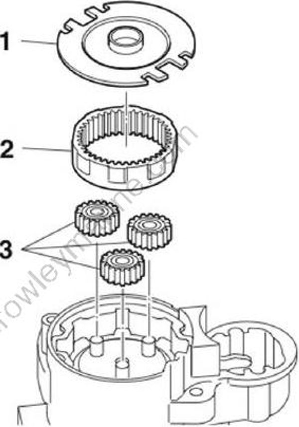
- Remove the plate “1”, outer gear “2”, and planetary gears “3”.
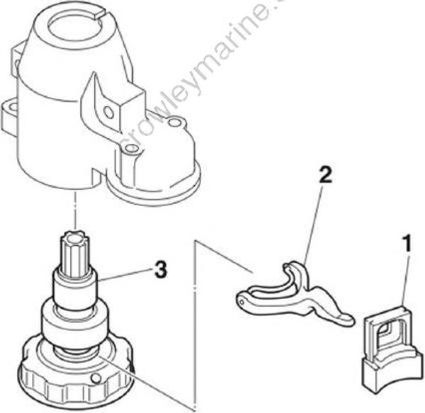
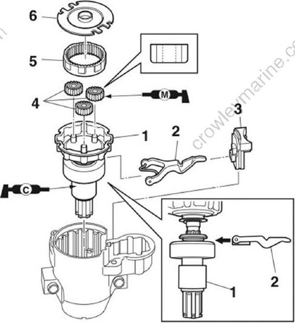
- Remove the rubber seal “1”, lever “2”, and pinion shaft assembly “3”.
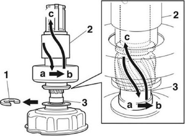
- Remove the E-clip “1”, and then remove the clutch assembly “2”.
TIP:
Push the clutch assembly “2” down completely onto the pinion shaft “3” in direction “a”, turn it one spline in direction “b”, and then remove it in direction “c”.
- Remove the shim “1”, bracket “2”, gasket “3”, and shim “4”.
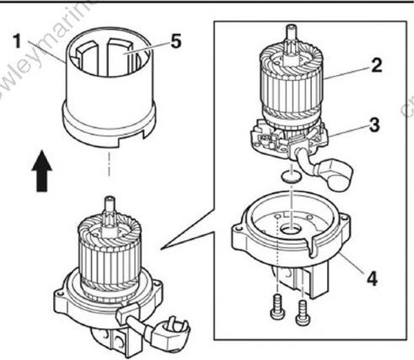
Remove the stator “1”.
Remove the armature “2” along with the brush holder assembly “3” from the bracket “4”.
NOTICE
Do not disassemble the stator.
Do not remove the magnets “5” from it.
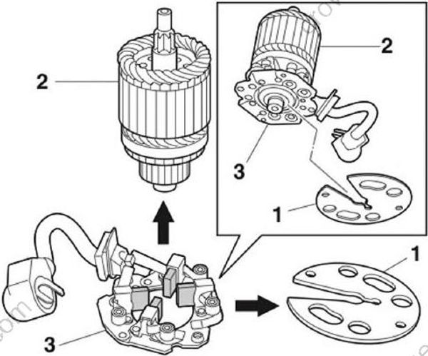
- Remove the plate “1”, and then remove the armature “2” from the brush holder assembly “3”.
Checking the armature (starter motor)
- Check the commutator.
Clean using 600-grit sandpaper and compressed air if dirty.

- Measure the commutator diameter “a”.
Replace the armature if below specification.
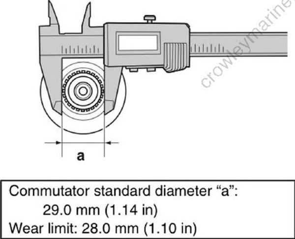
Commutator standard diameter "a": 29.0 mm (1.14 in)
Wear limit: 28.0 mm (1.10)
- Measure the commutator undercut “a”.
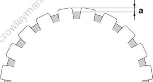
Commutator standard undercut “a”: 0.8 mm (0.03 in)
Wear limit: 0.2 mm (0.01 in)
- Check the armature for continuity.
Replace if out of specification.
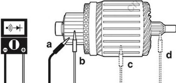
| Armature continuity: |
|---|
| Continuity: “a”-“b” No continuity: “a”-“c” “a”-“d” |
Checking the brush holder
- Check the brush holder assembly for continuity. Replace if out of specification.
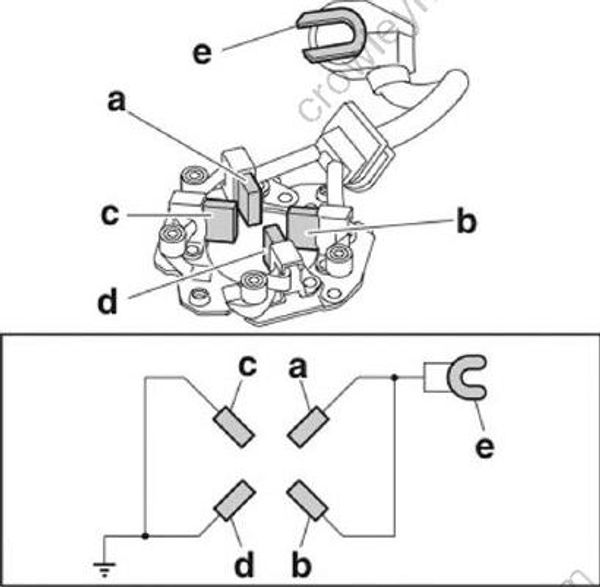
| Brush holder assembly continuity: |
|---|
| Brush “a”-Brush “b” Brush “a”-Terminal “e” Brush “b”-Terminal “e” Brush “c”-Brush “d” |
- Measure the length “a” of each brush.
Replace the brush assembly if below specification.
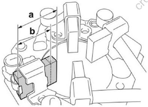
Brush standard length “a”: 15.5 mm (0.61 in)
Wear limit “b”: 9.5 mm (0.37 in)
Assembling the starter motor
NOTICE
Do not apply grease or oil to the commutator of the armature.
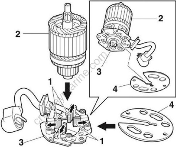
Push the brushes “1” into the holders, and then install the armature “2” to the brush holder assembly “3”.
Install the plate “4”.
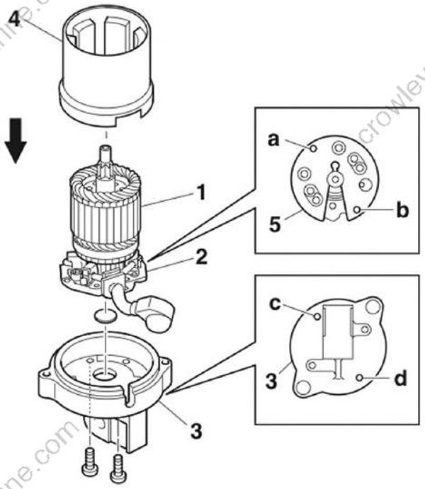
- Install the armature “1” along with the brush holder assembly “2” to the bracket “3”, and then install the stator “4”.
TIP:
Align the holes “a” and “b” in the plate “5” with the holes “c” and “d” in the bracket “3”.
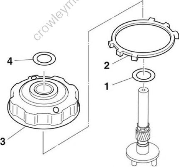
- Install the shim “1”, a new gasket “2”, the brackets “3”, and the shim “4”.
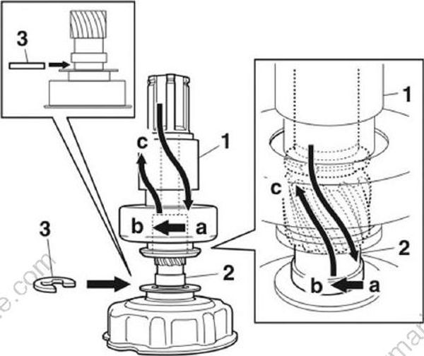
Push the clutch assembly “1” down completely onto the pinion shaft “2” in direction “a”, turn it one spline in direction “b”, and then slide it in direction “c”.
Install the E-clip “3”.
TIP:
Make sure that the clutch assembly “1” does not come out from the pinion shaft “2”.
- Install the pinion shaft assembly “1”, the lever “2”, a new rubber seal “3”, the planetary gears “4”, the outer gear “5”, and the plate “6”.
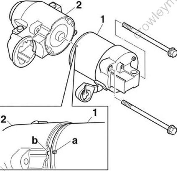
- Align the protrusion “a” on the stator “1” with the slot “b” in the cover assembly “2”, and then assemble the starter motor.
- Install the spring “1”, pinion “2”, pinion stopper “3”, and clip “4”.
- Install a new gasket “1”, the spring “2”, and the magnet switch “3”.
Installing the starter motor
- Install the starter motor to the power unit. See “Installing the starter motor” (7-25).
