INSPECTION AND REPAIR
Remove the brushes from the brush holder, and by tapping the frame end with a plastic hammer, remove the frame end.
Remove the armature from the frame end.

Armature
Frame end
Armature
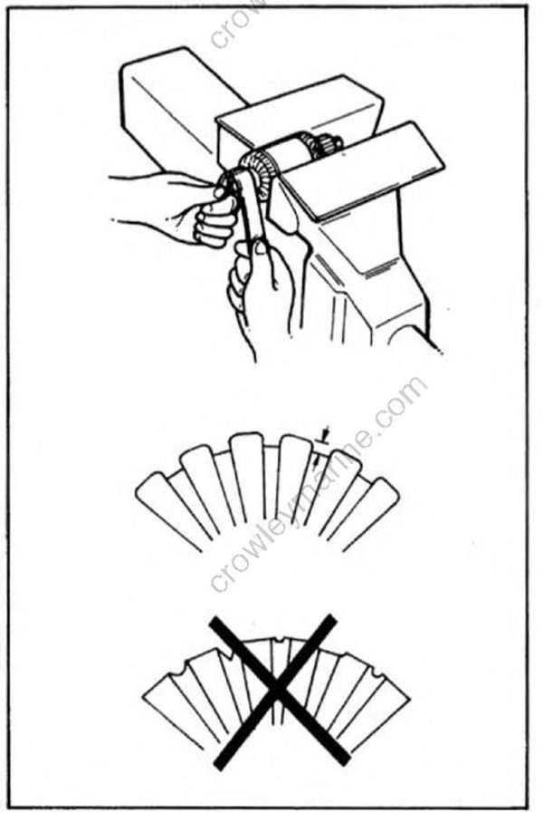
Check surfaces of the commutator. Using sandpaper (#500 or #600), smooth out any rough surface. If roughened excessively, turn the commutator in a lathe. If its run-out is 0.2 mm (0.008 in) or more, take the same step.
Measure the commutator mica undercut. If the depth is 0.2 mm (0.008 in) or less, cut it to the specification. Under cut:
0.4-0.8 mm (0.015-0.03 in)
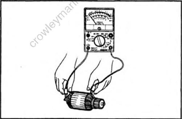
- Check continuity between the armature coil and ground.
If there is continuity, the armature coil is grounded and therefore, it should be replaced. 6-17
Field coil
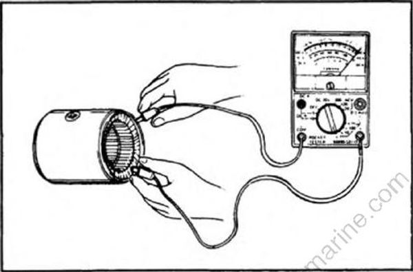
Check continuity between both terminals of the field coil. If there is no continuity, the wire is broken and the coil should be replaced.
Check continuity between either terminal of the field coil and the yoke. If there is continuity, the field coil is grounded and should be replaced.
Brushes
- Check wear on brushes. If worn more than limits, replace the brushes.
If brush springs are fatigued, replace them.
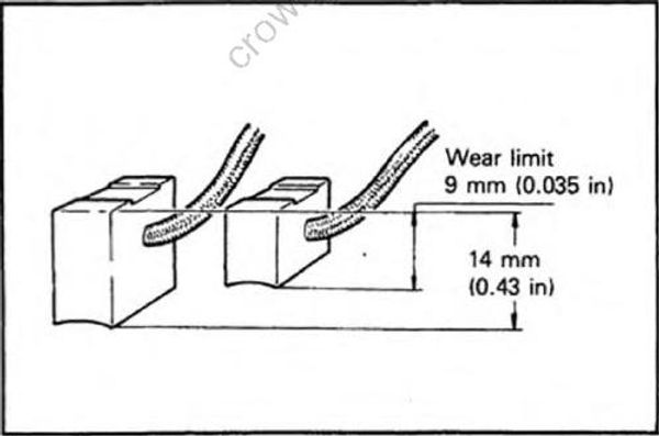
Check the brush holders for bends or dirty contact surfaces, and recondition or clean as required.
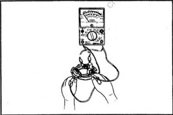
Check continuity between the insulated brush holder and ground. If there is continuity, brush holders are grounded and should be replaced.
Assembly
Armature
Force the connecter shaft side of the armature into the frame end.
When installing the armature assembly, be careful that the oil seal lip is not damaged.
Stator assembly
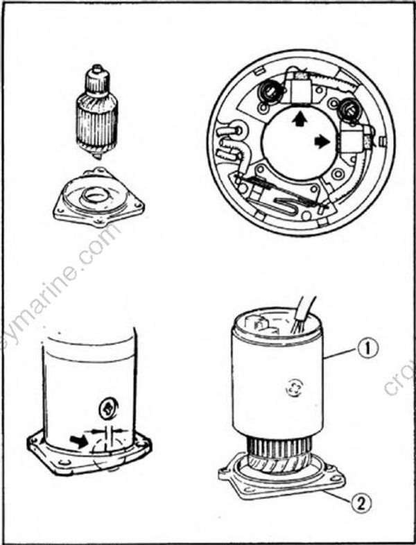
Put the armature into the stator, pull the bushes apart, and insert the commutator. Align the marks on the stator assembly and end frame and install the stator assembly.
1. Make sure the O-ring is correctly installed.
2. The marks should not be off each other more than 0.5 mm (0.02 in).
3. Take care not to scratch the commutator.
Stator assembly
Frame end
Commutator end frame
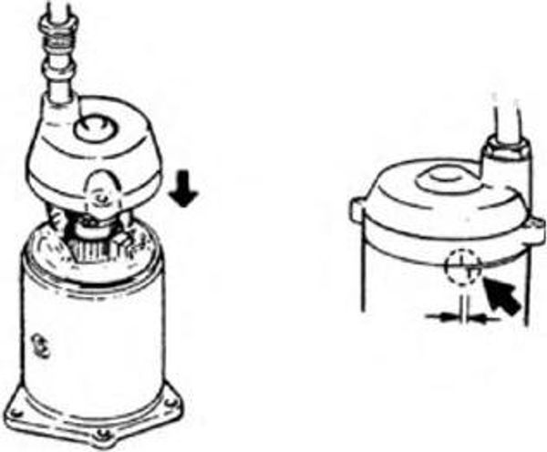
Align the marks on the end frame and armature assembly and install the end frame, then tighten the through-bolts.
Through-bolt tightening torque: 4 Nm (0.4 m-kg, 2.9 ft-lb)
1. Make sure the washer is installed.
2. The marks should not be off each other more than 0.5 mm (0.02 in).
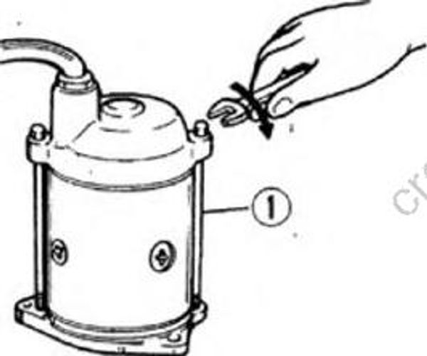
- Through bolt
Grommet
Screw the wire harness grommet into the commutator end frame.
Bolt tightening torque: 11 Nm (1.1 m«kg, 8 ft«lb)
Fit the grommet in the commutator end frame.
Test after assembling
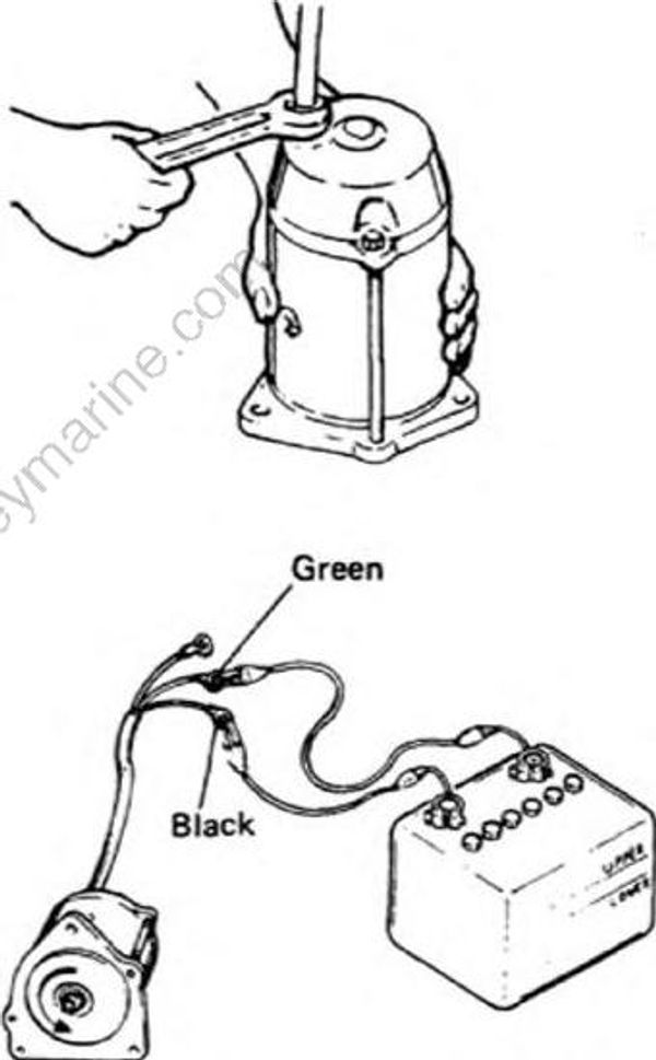
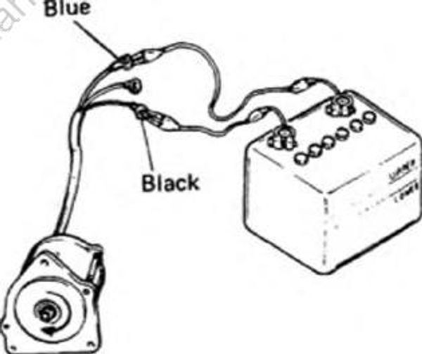
After assembling the motor, connect it to a battery, and make sure the motor operates smoothly.
| Battery (+) | Battery (-) | Rotational direction |
|---|---|---|
| Blue | Black | Right |
| Green | Black | Left |
Grease the oil seal lip and test the motor. Don't turn the motor continuously for more than 5 seconds.
Installation
Power trim sender
Removal
Refer to page 5-8.
Power trim and tilt up and down relay
Oil injection system inspection
Oil feed pump
To check the condition of the oil feed pump, the oil discharge must be measured. If the discharge is below specification, replace the oil feed pump assembly.
Oil discharge 200 ±70 cm3/min
The measurement of oil discharge should be made at a temperature of - 10°C (-34°F) or more, and the battery capacity should be 9V or more.
Air bleed of oil feed pump
Bleeding the oil feed pump
In the following case, the oil feed pump may possibly contain air. So bleed the pump.
When oil has been fed to the main oil tank by operating the emergency switch.
The sub-oil tank has more than 1.5 liters of oil, but no oil flows to the main oil tank even if the emergency switch is operated.
If the engine is run without oil in the main oil tank, it will seize up. Be sure to bleed the oil feed pump before operating the engine.
Bleeding procedure
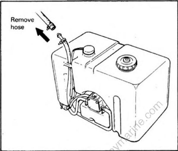
Take off the hose of the oil feed pump where it is attached to the pump; run the pump by turning on the main switch. Check to see if the pump actually pumps oil properly.
Sub-oil tank level gauge
Remove the level gauge from the sub-oil tank, and read the varying resistance while moving the float.
Float at the lowest position: ∞Ω
Float at the top position: 0Ω
Color: Black/Red: Black
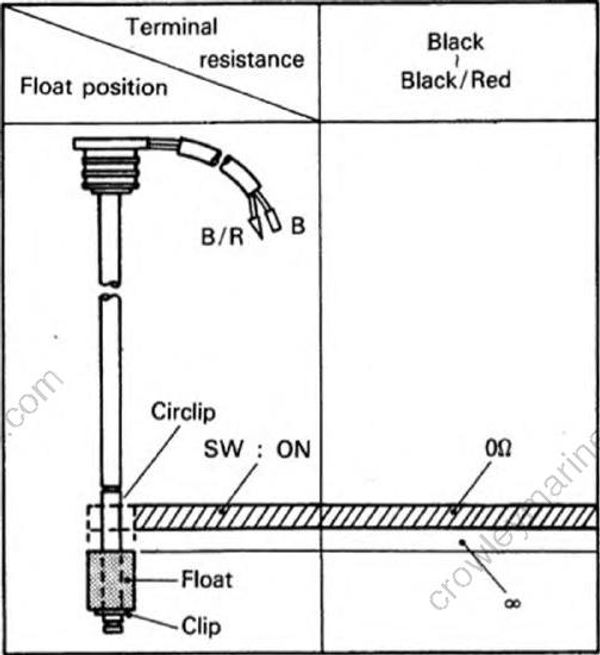
B/R : Black/Red
B : Black
Main-oil tank oil level gauge
Remove the oil level gauge from the main-oil tank.
Remove the circlip on the bottom end of the gauge, and remove the tube.
The relationship between the float position and resistance is as follows:
W : White
Br : Brown
R : Red
B : Black
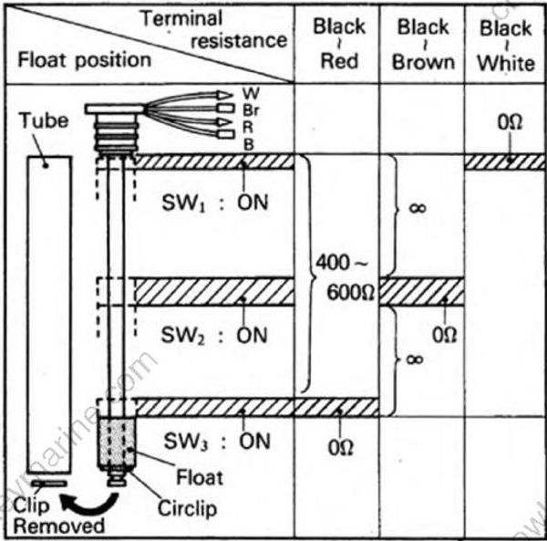
- If any element is broken, replace the entire unit.
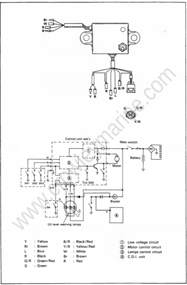
Control unit
Check the control unit as specified using the pocket tester.
If any element is broken, replace the entire unit.
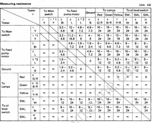
1. The resistance measured in this test should be used as reference.
2. Use the YAMAHA Pocket Tester (P/N), YU-3112) for this test.
If any other tester is used, the measurements will be unreliable
3. When checking the control unit, be sure to set the ohmmeter the Ω x 1k range.
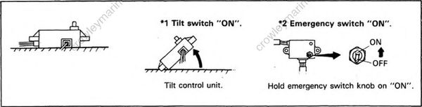
4. Make a measurement with the body placed in a horizontal position.