

BATTERY
If the battery shows the following defects, it should be replaced.
The battery voltage will not rise to a specific value nor will bubbles rise in any cell, even after many hours of charging.
Sulfation of one or more cells is indicated by the plates turning white or an accumulation of material in the bottom of the cell.
Specific gravity readings after a long, slow charge indicate a cell to be lower than any others.
Warpage or buckling of plates or insulator is evident.
Battery fluid is poisonous and dangerous, causing severe burns, etc. It contains sulfuric acid. Avoid contact with the skin, eyes, or clothing.
Antidote: EXTERNAL — Flush with water. INTERNAL — Drink large quantities of water or milk. Follow with milk of magnesia, beaten eggs, or vegetable oil. Call physician immediately.
Eyes: Flush with water for 15 minutes, and get prompt medical attention. Batteries produce explosive gases. Keep sparks, flame, cigarettes, etc. away. Ventilate when charging or using in an enclosed space. Always shield your eyes when working near battery.
KEEP OUT OF REACH OF CHILDREN.
The service life of a battery is usually two to three years. Lack of care, as described below, will shorten the life of the battery.
- Negligence in keeping battery topped off with distilled water;
- Battery left discharged;
- Over-charging with heavy charge;
- Freezing;
- Filling with tap water or sulfuric acid containing impurities;
Improper charging voltage or current on new battery.
If the outboard motor is not to be used for a long time, remove the battery and have it stored.
The following instructions should be observed:
Recharge the battery periodically.
Store the battery in a cool, dry place.
Recharge the battery before reinstallation.
| Battery | 12 Volt 70 |
|---|---|
| Electrolyte | 12 Volt 70 Amp-Hour |
| Electrolyte | Specific gravity: 1.280 |
| Initial charging current | 7 amp for 10 hours |
| Recharging current | Until specific gravity reaches 1.280 |
| Refill fluid | Distilled water to maximum level line |
Checking other electrical parts of the power unit
Thermo switch
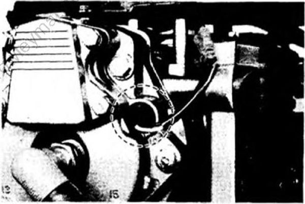
- Remove the thermo switch from the cylinder head.
1. Handle the thermo switch very carefully. Never let it drop or give it a strong shock. Should it be dropped, it must be replaced.
2. Avoid submerging the thermo switch during the test, or malfunctions may result.
- Immerse the thermo switch in the water as shown. While heating the water, check the continuity at each temperature. If the thermo switch will not operate as shown in the table below, the thermo switch is faulty. It should be replaced.
| Test step | Water temperature | Pocket tester (Ω x 1) |
|---|---|---|
| 1 | 0 ~ 87° ± 3°C (32 ~ 188.6 ± 37.4°F) | Discontinuity |
| 2 | more than 88° ± 3°C (more than 190.4 ± 37.4°F) | Continuity |
| 3* | 88° ± 3 ~ 68 ± 7°C (190.4 ± 37.4 ~ 154.4 ± 45°F) | Continuity |
| 4* | less than 67° ± 7°C (less than 152.6 ± 45°F) | Discontinuity |
- When the water begins boiling in tests 3 and 4, stop heating the water and allow it to cool down, then start the test again.
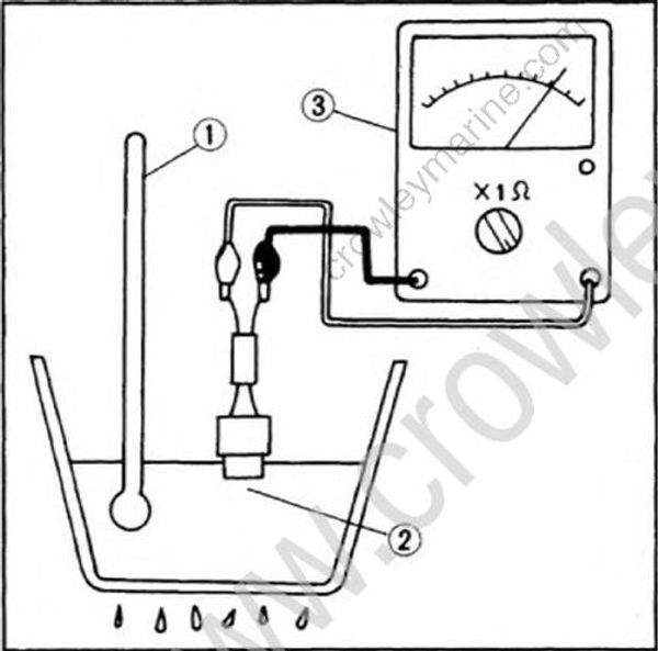
1. Temperature gauge
2. Thermoswitch
3. Pocket tester
- Install the thermo switch into the cylinder head.
Avoid pushing the thermo switch hard into the cylinder head, or leads may break at soldered areas.
Wire harness
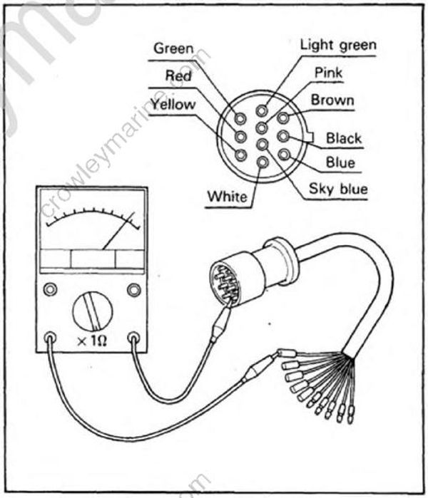
Using the Pocket Tester, check the continuity of the wire harness between the switch panel and the engine.
Make sure all the wires are connected to the 10-P plug correctly. The wires and pins of identical colors must be connected, or no continuity test can be made.
If any one of the wires has no continuity, replace the wire harness.
Choke solenoid
Disconnect the choke solenoid leads from the choke solenoid and wire harness.
Check the choke solenoid as specified using the pocket tester.
Continuity........................Normal
Discontinuity............................Defective
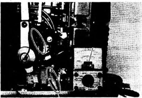
- If the element is broken, replace the en tire unit.
Installation
Refer to page 4-41.
LOWER UNIT AND RELATED PARTS
Power trim and tilt motor
Removal
Refer to page 5-18.
Disassembly
Loosen the wire harness bolt, and remove the two bolts securing the frame end.
Remove the commutator end by tapping on it with a plastic hammer.
1. Remove the lead wire while taking care not to break it.
2. Spray WD-40 on the lead, so the frame can easily be removed.
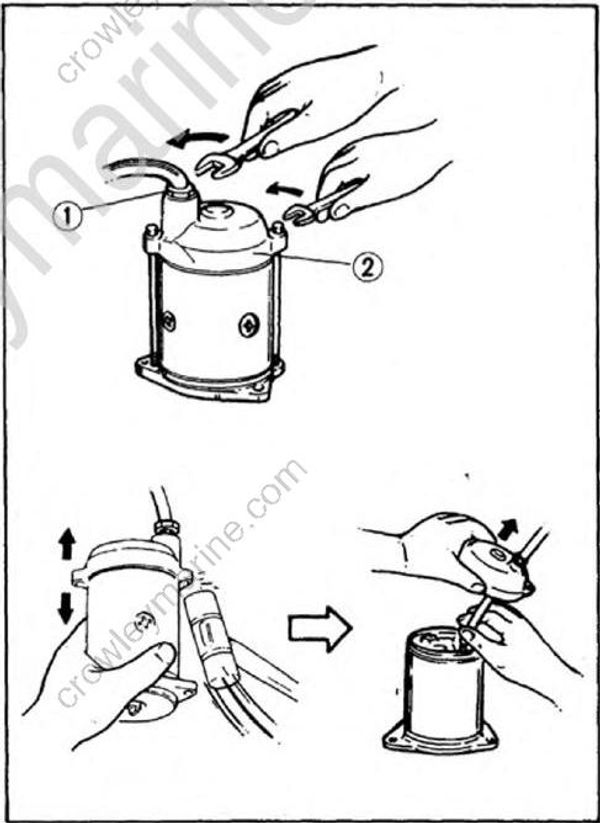
- Wire harness bolt
- Commutator end
