

Preface
This trim/tilt switch connects in parallel with trim/tilt switch on the motor for convenient remote operation. It is used on 60 TTL models CE and newer.
Step 1. Preparation for Installation

[1]
1. Check kit to become familiar with contents.
| Ref. | Name of Part | Qty. |
|---|---|---|
| 1 | Bezel | 1 |
| 2 | Switch Assembly | 1 |
| 3 | Cable Assembly | 1 |
| 4 | Nut | 1 |
| 5 | Washer | 1 |
| 6 | Screw | 2 |
2. Read installation instructions completely prior to starting work.
3. Obtain hand tools and items required for installation.
Tools Required:
Electrical Drill
2-1/8 in. (54 mm) Hole Saw
3/4 in. Wrench
Phillips Screwdriver
Step 2. Select Location for Trim/Tilt Switch
1. Select a mounting location that is flat, within reach of the cable assembly and convenient for operation. If a suitable mounting location is not available, a mounting bracket can be made.
2. Mark mounting location center and cut 2-1/8 in. (54 mm) diameter hole using a hole saw.
3. Place bezel in hole, mark screw locations and drill 3/32 in. (4 mm).
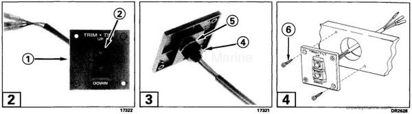
Step 3. Trim/Tilt Switch Installation
[2]
1. Assemble switch (2) to bezel (1) as shown.
[3]
2. Install washer (5) and nut (4). Tighten nut securely.
[4]
3. Place bezel and switch assembly into mounting hole, install screws (6) and tighten securely.
Step 4. Connecting Cable

Disconnect battery cables before making cable connections to prevent damage to electrical components.
[5]
1. Locate wire connectors for motor mounted trim/tilt switch as shown.
[6] [7]
2. Disconnect bullet connectors and attach cable as shown.
The trim/tilt switches are wired in parallel. Connect matching color wires.
3. Route cable out of lower engine cover through grommet to the second trim/tilt switch.
Secure switch cable to motor cable, leaving enough slack to allow turning of motor.
4. Attach cable to switch.
Step 5. Installation Check
1. Connect battery cables.
2. Check "UP" and "DOWN" operation. If operation is reversed check matching of blue and green wires.