

PREFACE
This kit moves the emergency stop switch from two non-trim 1996 (ED) and newer surface mount remote controls to a single dash mounted switch. This kit is compatible with the Modular Wiring System.

[1]
Contents of Kit
| Ref. | Name of Part | Qty. |
|---|---|---|
| 1 | Switch Nut | 2 |
| 2 | Switch Cable | 1 |
| 3 | Bezel | 1 |
| 4 | Nut | 1 |
| 5 | Screw | 2 |
| 6 | Tie Strap | 4 |
| 7 | Lanyard and Clip | 1 |
Remove and discard original lanyards.
[2]
Remove both existing key switch nuts (A), and replace with switch nuts (1). Tighten with a 15/16 in. socket to a torque of 20-30 in. lbs. (2,3-3,4 Nm).

[3] [4]
If boat surface will be next to starboard side of control at (B), remove the handle cover (C) from the starboard control. Reinstall handle (D) on the starboard side of the starboard control.
[5] [6]
If boat surface will be next to port side of control at (E), remove the handle cover (F) from the port control. Move handle (G) on starboard control to the starboard side of the control.
To remove handle and remove cover from handle, refer to the Accessory Service Manual for procedures.
Install Remote Controls
Purchase a dual remote control installation kit and install remote controls following instructions in that kit.
The control handles on dual remote controls must not be moved on the splines, or the mounting bolts will restrict throttle movement. With the controls in NEUTRAL, the control handles must be vertical when the controls are horizontal.
Connect Switch Cable to Remote Controls

[7]
Connect one pair of the switch cable (2) six-socket plugs (A) and six-pin receptacles (B) to the starboard remote control receptacle (C) and starboard motor wiring harness (D). Connect the other switch cable pair to the port remote control and port motor wiring harness.
Install Dash Bezel and Emergency Stop Switch
[8]
Place the bezel (3) at the selected location. Turn the bezel over, face against dash, and rotate so holes are at top left and bottom right. Mark switch and mounting screw holes.
[9]
Center punch and drill three 3/32 in. 2,4 mm) holes. Enlarge switch hole with a 1-1/2 in. (38 mm) hole saw.
[10]
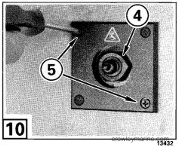
Pull emergency stop switch through dash and insert into bezel. Install nut (4) on switch and tighten to a torque of 20-30 in. lbs. (2,3-3,4 Nm).
Position bezel with emergency stop switch symbol at the top. Fasten bezel tom mounting surface with two screws (5).
Coil extra length and secure harness under dash with tie straps (6).
Test Switches
Attach a lanyard clip (7) to the emergency stop switch.
Start the starboard motor. Shift motor into gear and out of gear, trim motor in and out, and stop motor with key switch. If the starboard remote control does not control all functions of the starboard motor, check for improper connection of switch cable to motor wiring harnesses and remote control electrical cables.
Test emergency stop switch every 30 days.
Start both motors, then stop motors by pulling clip from the stop switch. If both motors do not stop, repair stop switch before operating boat.