

Electronic control system
This model uses an electronic fuel injection control, ignition timing control, engine speed control, ISC valve control, and fail-safe.
The engine ECM performs these controls based on data received from each sensor and switch.
The engine ECM is equipped with a self-diagnosis function. This function is used to diagnose failures using the YDIS.
This model can be equipped with Y-COP as an anti-theft measure (optional).
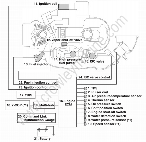
*1. Optional
- TPS
- Pulser coil
- Air pressure/air temperature sensor
- Thermo sensor
- Oil pressure switch
- Shift position switch
- Engine shut-off switch
- Water detection switch
- Water pressure sensor
- Speed sensor
- Ignition coil
- Vapor shut-off valve
- Fuel injector
- High-pressure fuel pump
- ISC valve
- Engine ECM
- YDIS
- Y-COP
- Multi-hub
- Command Link Multifunction Gauge
- Battery
- Fuel injection control
- Ignition control
- ISC valve control
Engine ECM components
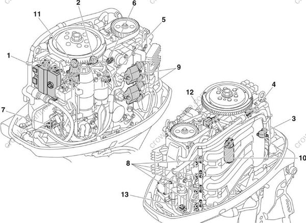
| Part name | Function |
|---|---|
| 1. Engine ECM | Determines the engine operating conditions according to the input signals from the sensors which are installed at various locations on the engine, and sends output signals to operate the actuators to perform the various control functions. |
| 2. Pulser coil | Detects the engine speed. |
| 2. Pulser coil | Detects the crankshaft rotation angle |
| 3. TPS | Detects the throttle valve opening. |
| 4. Air pressure/air temperature sensor | Detects the intake air pressure and intake air temperature |
| 5. Oil pressure switch | Detects oil pressure decrease. |
| 6. Thermo sensor | Detects cooling water temperature. |
| 7. Shift position switch | Detects the neutral position. |
| 8. Fuel injector | Injects fuel to the intake port. |
| 9. Ignition coil | Produces high voltage to ignite a spark plug. |
| 10. High-pressure fuel pump | Pressurizes the fuel and sends the fuel to the fuel rails. |
| 11. ISC valve | Adjusts the flow of air to the engine when idling |
| 12. Vapor shut-off valve | Controls the amount of vapor gas to be sent from the vapor separator to the intake system. |
| 13. Water detection switch | Detects water intrusion in fuel filter. |
ECM
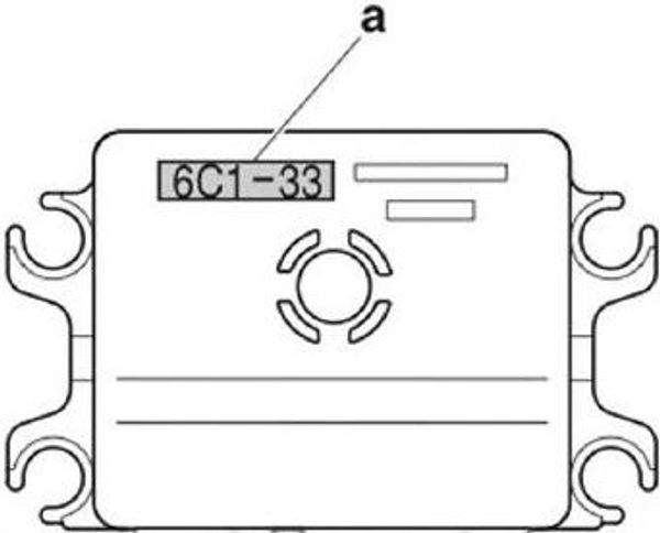
The ECM shape is the same for all models.
The ECM specifications differ depending on the destinations. Identify the ECM by the ECM ID “a”.
| Model name | ECM ID “a” |
|---|---|
| F50B, T50B | 6C1-33 |
| F60B, T60B | 6C5-33 |
Electronic fuel injection control
The engine ECM switches the control mode between the start-up mode, normal operating mode, and fuel injection cut-off mode according to the signals from the sensors. In addition, various compensations are made to determine the actual fuel injection timing and fuel injection amount. Additionally, when the engine start switch is turned to ON, the engine ECM moves the injectors once before activating the high-pressure pump relay to prevent them from sticking.
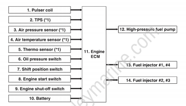
- Pulser coil
- TPS
- Air pressure sensor
- Air temperature sensor
- Thermo sensor
- Oil pressure switch
- Shift position switch
- Engine start switch
- Engine shut-off switch
- Battery
- Engine ECM
- High-pressure fuel pump
- Fuel injector #1, #4
- Fuel injector #2, #3
*1. Sensors used for compensations.
| Mode | Control items | Controls performed by ECM |
|---|---|---|
| Start-up mode | Synchronized injection when cylinders are not identified | To improve engine starting, fuel is injected into all cylinders simultaneously in synchrony with the signal from the pulser coil until the cylinders have been identified. |
| Start-up mode | Simultaneous injection into all cylinders when starting | When cylinders have been identified and the engine is running at less than 500 r/min, fuel is injected into all cylinders simultaneously, based on BTDC 100°. |
| Normal operating mode | Synchronized injection by group when running normally | Fuel injection completion timing is set based on the exhaust TDC for both #1, #4, and #2, #3 cylinder groups |
| Normal operating mode | Asynchronous injection during acceleration | During acceleration, when the TPS or the air pressure sensor signal exceeds the set figure, fuel is injected into all cylinders without being synchronized with the pulser coil signal. |
| Fuel injection cut-off mode | Cutoff when engine shut-off switch is on | Fuel injection is cut when the clip is removed (engine shut-off switch: ON). |
| Fuel injection cut-off mode | Cutoff when overrewing | To protect the engine, fuel injection is skipped when the engine speed is more than 6200 r/min |
| Fuel injection cut-off mode | Cutoff due to activation of Y-COP | Fuel is not injected when the engine is locked by Y-COP. When a communication error occurs, fuel flow is cut to control engine speed. |
Ignition timing control
This model uses group ignition for cylinders #1 and #4, and for cylinders #2 and #3.
The engine ECM switches the control mode between the start-up mode, normal operating mode, and ignition cut-off mode according to the signals from the sensors.
In addition, various compensations are made to determine the actual ignition timing and the energization time of current to the ignition coil.
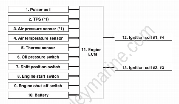
- Pulser coil
- TPS
- Air pressure sensor
- Air temperature sensor
- Thermo sensor
- Oil pressure switch
- Shift position switch
- Engine start switch
- Engine shut-off switch
- Battery
- Engine ECM
- Ignition coil #1, #4
- Ignition coil #2, #3
*1. Sensors used for compensations.
| Mode | Control items | Controls performed by ECM |
|---|---|---|
| Start-up mode | Ignition timing when starting | Ignition occurs at BTDC 10° when the engine is running at less than 500 r/min |
| Normal operating mode | Normal ignition timing | Ignition timing is set based on signals from the pulser coil and the TPS, and all necessary compensations are made. |
| Ignition cut-off mode | Ignition cutoff when engine shut-off switch is on | Ignition is cut when the clip is removed (engine shut-off switch: ON). |
| Ignition cut-off mode | Ignition cutoff when over-revving | To protect the engine, ignition is skipped when the engine speed is more than 6200 r/min. |
| Ignition cut-off mode | Ignition cutoff due to activation of Y-COP | Ignition does not take place when the engine is locked by Y-COP. When a communication error occurs, ignition is cut to control engine speed. |
Engine speed control
The engine ECM controls ignition and fuel injection as necessary to prevent damage to the engine when engine speed is more than a predetermined level, when the engine overheats, or if oil pressure decrease is detected. Fuel injection is cut together when ignition in the grouped cylinders has been cut completely.
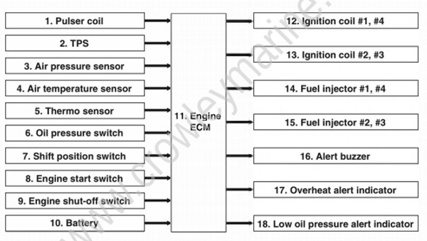
- Pulser coil
- TPS
- Air pressure sensor
- Air temperature sensor
- Thermo sensor
- Oil pressure switch
- Shift position switch
- Engine start switch
- Engine shut-off switch
- Battery
- Engine ECM
- Ignition coil #1, #4
- Ignition coil #2, #3
- Fuel injector #1, #4
- Fuel injector #2, #3
- Alert buzzer
- Overheat alert indicator
- Low oil pressure alert indicator
| Control name | Condition | Controls performed by ECM |
|---|---|---|
| Over-revolution control | When the engine speed is more than 6200 r/min. | The fuel injection and ignition are cut off in a predetermined cylinder order. |
| Overheat control | Control starts when the cooling water temperature reaches 80 °C (176 °F). Overheating is not detected until the engine speed reaches and stays at 2000 r/min or higher for 24 seconds after the engine was started, or until 79 seconds have passed since the engine was started. | Firing and fuel injection will be controlled to limit engine speed to approximately 2600 r/min. The overheat alert indicator comes on, and the alert buzzer sounds. Control stops when the cooling water temperature is 69 °C (156 °F) or less. |
| Low oil pressure control | If the oil pressure switch is on, low oil pressure is detected when the cooling water temperature has reached 40 °C (104 °F), or the engine speed has reached and stays at 1398-1500 r/min or higher. | Firing and fuel injection will be controlled to limit engine speed to approximately 2600 r/min. The low oil pressure alert indicator comes on, and the alert buzzer sounds. |
ISC valve control
The engine ECM adjusts the ISC valve opening so that engine speed is maintained at a target value when idling. When the engine shut-off switch is ON, fuel injection is halted.
Trolling speed can be adjusted from 620-900 r/min by opening and closing the ISC valve using the Command Link Multifunction Gauge or the tiller handle (with trolling switch) when the gear shift lever is in the F or R position.
However, when the gear shift lever is set to the N position or when the throttle is opened and engine speed is more than 3000 r/min, the trolling speed control function is deactivated.
Alert indicator, alert buzzer control
The alert indicator lights and the buzzer sounds under the following conditions.
| Control name | Condition |
|---|---|
| Alert indicator control | Overheated |
| Alert indicator control | Low oil pressure |
| Alert buzzer control | Overheated |
| Alert buzzer control | Low oil pressure |
| Alert buzzer control | Water in the fuel filter when the gear shift lever is in the N position |
| Alert buzzer control | Engine cranked when the clip is removed from the engine shut-off switch. |
Fail-safe
The engine ECM enters the fail-safe mode when an electrical component malfunctions. The fail-safe system records the trouble codes according to the engine trouble conditions.
| Trouble code | Item | Trouble conditions to be detected | Control and operation |
|---|---|---|---|
| 15 | Thermo sensor | Open or short circuit in the thermo sensor circuit. Output voltage is less than 0.1 V or more than 4.52 V. | Control is performed based on the intake air temperature when starting. Set to 40 °C (104 °F) when running. High engine idle speed. |
| 18 | TPS | Open or short circuit in the TPS circuit. Output voltage is less than 0.3 V or more than 4.7 V. | Control is performed based on the intake air pressure. |
| 19 | Battery voltage | Voltage is 12 V or less for 2 minutes, even when engine speed is 2000 r/min or more | High engine idle speed. |
| 23 | Air temperature sensor | Open or short circuit in the air temperature sensor circuit. Output voltage is less than 0.1 V or more than 4.61 V | Set to 40 °C (104 °F). High engine idle speed. |
| 27 | Water in fuel filter | The shift position switch is on and the water detection switch is on. | The alert buzzer sounds. |
| 28 | Shift position switch | Cranking while in gear. Cranking while the shift position switch circuit is open-circuited. | ECM does not control. |
| 29 | Air pressure sensor | Open or short circuit in the air pressure sensor circuit. Output voltage is less than 0.2 V or more than 4.5 V | Control is performed based on the TPS. High engine idle speed |
| 37 | Intake air passage | The shift position switch is off, the throttle is fully closed, the ISC valve is fully closed, and the engine speed is more than 1100 r/min | Throttle valve is set at specified opening angle. |
| 44 | Engine shut-off switch | Cranking when the clip is removed. | Fuel injection is cut. |
| 49 | Over cooling | Cooling water temperature is 40 °C (104 °F) or less, and engine speed is 3000 r/min or more for 2 minutes or more. | ECM does not control. |
| 86 | Immobilizer (Y-COP) | Open or short circuit in the Y-COP circuit. Communication error continues for more than 3 seconds | The engine will start, but engine speed is limited to 2000-3500 r/min. |
