

Preface
This stop switch kit will service all Johnson® and Evinrude® outboards with a stop switch in the tiller handle.
The installation of this kit requires special tools and involves procedures described in detail in the Service Manual for your product. If you do not have and do not wish to purchase the tools and literature required, have this kit installed by your Evinrude/Johnson Dealer.
Step 1. Prepare for Installation
Read all the instructions before starting work.
[1]
Review contents of kit:
| Ref. | Name of Part | Qty. |
|---|---|---|
| 1 | Switch Assembly | 1 |
| 2 | Pin Terminal | 1 |
| 3 | Socket Terminal | 1 |
| 4 | Ring Terminal | 1 |
| 5 | Grease | 1 |
Collect necessary tools and supplies:
Common hand tools
Wire cutter-stripper-crimping pliers
Amphenol removal and installation tools
Twist-Grip™ Remover P/N 0390767
Step 2. Remove Old Switch
Refer to Midsection - Steering Handle Servicing in Service Manual for disassembly procedures.
Step 3. Attach Terminals
[2]
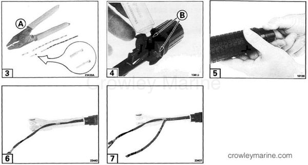
Compare wire lengths and terminal ends of old switch and new switch (1). If wires on new switch are longer cut them to length of old switch wires. Push end of braided sleeve off wires and cut the same amount off the sleeve (A) so sleeve remains 8 inches shorter than wires. Heat the cut end of sleeve to prevent fraying. If either terminal is different that terminal must be removed and the correct one installed.
Braided sleeve cannot be PULLED off wires. Braided sleeve must be PUSHED off and on wires to move it.
[1] [3]
If either terminal must be replaced, or the leads shortened, strip about 3/16 in. (5 mm) of insulation from wire. select terminal from kit that is the same as on the old switch wire.
[1] [3]
Attach the Amphenol pin (2) and/or socket (3) with the Crimping Pliers (A) as required to duplicate the original terminal configuration.
[1]
Attach the ring terminal (4), if required, with a universal type crimping pliers.
If you are not sure you have a good mechanical and electrical connection on any of the terminals, solder the terminals to the wires.
Step 4. Install Switch
Refer to Midsection - Steering Handle Servicing in Service Manual for reassembly procedures.
[4]
Lubricate the switch shoulder between the four tabs (B) (surface under the tabs) before installing the grip over the stop switch on the steering handle. Use the supplied lubricant (5).
[5]
Starting with the stop switch assembled in the handle, screw idle stop switch all the way out (counterclockwise).
[6]
Push braided sleeve against switch and wrap leads around throttle cable, using only two evenly spaced and flat spirals. Secure with tape as shown.
[7]
If used, apply spiral wrap starting at the twist grip.
Step 5. Test switch
Start motor and push stop button to stop motor. If motor does not stop repair as required.