

System Check CIRCUIT TESTS
Make sure the System Check engine monitor can alert the operator during a “NO OIL,” “WATER TEMP” or “HOT,” “CHECK ENGINE,” or “LOW OIL” condition. Check the condition of the warning system and associated wiring and connections. Test the engine monitor regularly and anytime you suspect an alert situation has been missed. The instrument harness must be connected to the outboard before performing the following tests. Refer to the Engine Wiring diagram and the MWS Instrument Wiring diagram in the back of this manual.
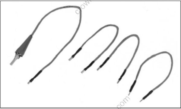
IMPORTANT: Use jumper wires made with the appropriate terminals to test the warning circuits.
Gauge Self-Test Check
Turn the key switch to ON with the outboard NOT running. The gauge warning lights for NO OIL, WATER TEMP, CHECK ENGINE, and LOW OIL must all light at once, then turn off in sequence, and the warning horn must sound for one-half second.
If the gauge lights do not turn on, turn the key switch OFF. Disconnect the gauge 8-pin connector from the back of the gauge and turn the key switch ON. Test for battery voltage between instrument harness terminal 1 (purple wire) and terminal 2 (black wire).
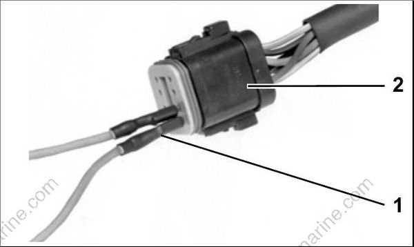
- Test adapter(s)
- Connector, System Check gauge
• If battery voltage is present, replace the gauge.
• If there is no battery voltage, check that 12 V is present at terminal “B” of the key switch. Check condition of the instrument harness, key switch, and connections. If the lights worked, but the warning horn did not sound for one-half second, turn the key switch OFF. Disconnect the warning horn 2-pin connector. Substitute a known good warning horn. Turn the key switch ON.
• If the substitute horn beeps, the original horn is defective and must be replaced.
• If the substitute horn does not beep, check for battery voltage between instrument harness 2- pin connector, terminal 2 (purple wire) and ground with the key switch ON. Also, check the tan/blue wire for continuity between pin 8 of the 8-pin connector and pin 1 of the 2-pin connector.
• If battery voltage is present at the purple wire and the tan/blue wire has continuity between
two connectors, replace System Check the gauge.

- Purple wire
- Tan/blue wire
Turn the key switch OFF and reconnect all disconnected circuits.
CHECK ENGINE Circuit Test
Separate the 6-pin System Check connector of MWS instrument harness from engine harness. Black wire (pin 3) must be grounded. Using a jumper wire, connect tan/orange wire (pin
2) to a clean engine ground. Turn the key switch ON. After the normal self-test sequence, the CHECK ENGINE light should stay on.
• If the CHECK ENGINE light is not on, test circuit for continuity. Check continuity of the MWS instrument harness (tan/orange wire).
• Check continuity of the engine wire harness between terminal 2 (tan/orange wire) of the System Check connector and pin 17 of the EMM J1- A connector. Turn the key switch OFF and reconnect all disconnected circuits.
WATER TEMP/ HOT Circuit Test
The tan wire of engine harness and the MWS harness receives a signal from the EMM. The EMM receives information from the temperature sensor on the cylinder head. Using a jumper wire, connect tan wire (pin 6) of the engine harness connector to a clean engine ground.

Turn the key switch ON. After the normal self-test sequence, the gauge WATER TEMP / HOT indicator should stay on.
• If LED is not on, test circuit for continuity. Test for continuity of both the engine harness (tan wire) and the MWS instrument harness (tan wire).Turn the key switch OFF and reconnect all disconnected circuits.
IMPORTANT: To test the temperature sensor itself, refer to Engine Temperature Sensor Test on p. 128.
LOW OIL Circuit Test
Turn the key switch ON. Using a jumper wire, connect tan/black wire (pin 4) of the engine harness connector to a clean engine ground. The LOW OIL light should turn on after 40 seconds.
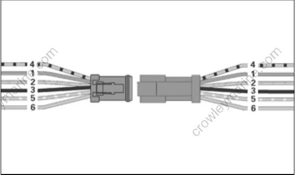
If the LOW OIL light does not turn on after connecting the terminal to ground, test circuit for continuity.
Turn the key switch OFF and reconnect all disconnected circuits.
NO OIL Circuit Test
Separate the 6-pin System Check connector of MWS instrument harness from engine harness. Black wire (pin 3) must be grounded. Using a jumper wire, connect tan/yellow wire (pin 5) to a clean engine ground. Turn the key switch ON. After the normal self-test sequence, the NO OIL light should stay on.
- If the NO OIL light is not on, test circuit for continuity. Test for continuity of the MWS instrument harness (tan/yellow wire).
- Test for continuity of the engine wire harness between terminal 5 (tan/yellow wire) of the System Check connector and pin 24 of the EMM J1 A connector.
Turn the key switch OFF and reconnect all disconnected circuits.
REMOTE CONTROL SWITCH TESTS
Key Switch Test
Refer to Wiring Diagrams at back of manual. Use an ohmmeter or a continuity light to test key switch operation. Replace switch if results are incorrect with any of the following tests.
IMPORTANT: Disconnect battery and key switch wiring before proceeding with the following tests.
STEP 1
Stop/Ground Terminals (M) – Connect meter between the two “M” terminals. Meter must indicate NO continuity at START or ON. Turn key switch OFF. Meter must indicate continuity.
STEP 2
Accessory Terminal (A) – Make sure the key switch is OFF. Connect the ohmmeter or continuity light between terminals “B” (battery) and “A” (accessory) of key switch. Meter must indicate NO continuity. Turn switch ON. Meter must indicate continuity. Turn key switch to START. Meter must continue to indicate continuity.
STEP 3
Starter Terminal (S) – Hold key switch at START. Connect meter between terminal “B” and terminal
“S.” Meter should indicate continuity.
IMPORTANT: The choke function or terminal “C” of the key switch is NOT used.
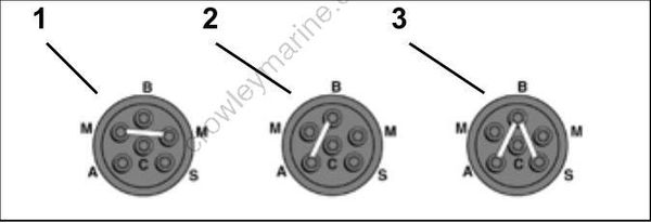
- OFF
- ON
- START
