

BATTERY CHARGING SYSTEM
OUTLINE
The battery charging system circuit is illustrated below.
It is composed of the battery charge coil, the rectifier & regulator and the battery.
The three phase AC current generated from the battery charge coil is converted by the rectifier & regulator into regulated DC current which is used to charge the battery.
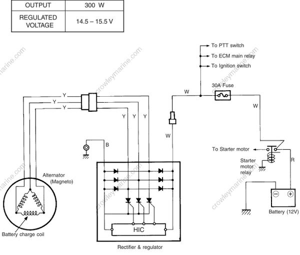
Battery charge coil resistance
INSPECTION
BATTERY CHARGE COIL
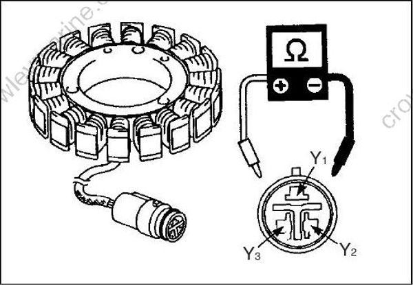
09930-99320: Digital tester
Tester range: Ω (Resistance)
Disconnect the battery charge coil wire from the rectifier & regulator.
Measure resistance between the terminals for all combinations.
| Terminal for testerprobe connection | Resistance |
|---|---|
| Yellow 1 to Yellow 2 | 0.3 – 0.5 Ω |
| Yellow 1 to Yellow 3 | 0.3 – 0.5 Ω |
| Yellow 2 to Yellow 3 | 0.3 – 0.5 Ω |
If the measurement is out of the specification, replace the bat tery charge coil.
RECTIFIER & REGULATOR
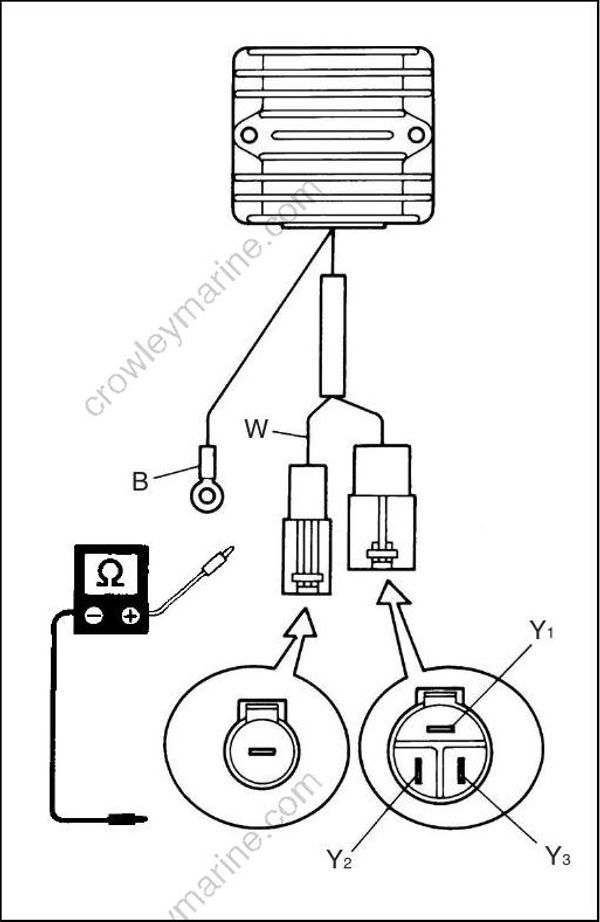
09930-99320: Digital tester
Tester range: Ω (Resistance)
Disconnect all wires of the rectifier & regulator.
Measure resistance between the terminals for all combinations.
The values given below are for the SUZUKI digital tester. As thyristors, diodes, etc. are used inside this rectifier & regulator, the resistance values will differ when an ohmmeter other than the SUZUKI digital tester is used.
Rectifier & regulator resistance
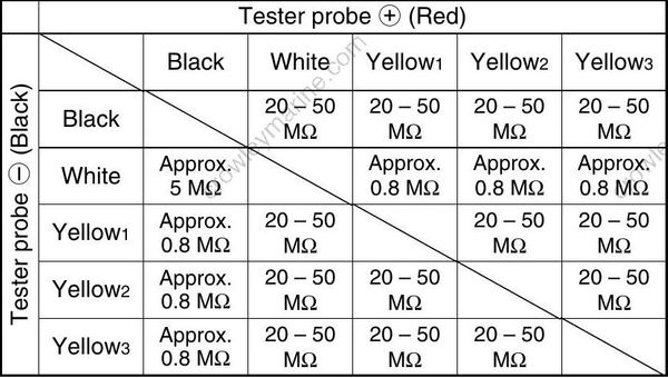
If the measurement is out of the specification, replace the rectifier & regulator.
REMOVAL/INSTALLATION
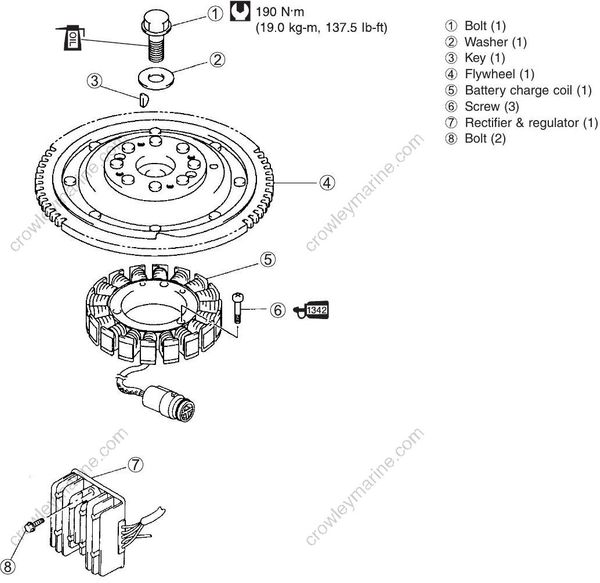
(1) Bolt (1)
(2) Washer (1)
(3) Key (1)
(4) Flywheel (1)
(5) Battery charge coil (1)
(6) Screw (3)
(7) Rectifier & regulator (1)
(8) Bolt (2)
REMOVAL
Before removing electrical parts:
• Disconnect battery cables from battery
Battery charge coil
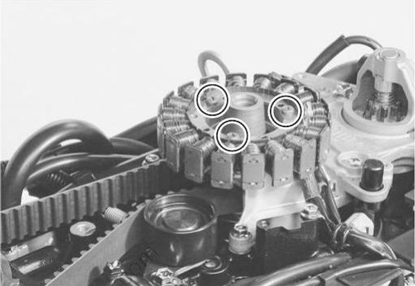
- Remove the flywheel. (See page 3-52.)
- Remove the three screws.
- Disconnect the battery charge coil lead wire.
Rectifier & regulator
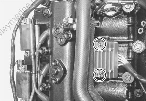
- Remove the electric parts holder. (See page 4-17.)
- Remove the two bolts.
INSTALLATION
Installation is reverse order of removal with the special attention to the following step.
Battery charge coil
Apply the thread lock to the coil securing screws.
99000-32050: THREAD LOCK “1342”
