

General Description
Ignition System Description
The ignition system is composed of a flywheel magneto, igniter unit, spark plug and emergency & engine stop switch:
- The igniter is a single unit that consists of the ignition parts, ignition control circuit and voltage supply circuit.
- When the reluctor bar (magnet), which is installed in the flywheel, passes the igniter unit, the exciter coil in the unit generates electrical energy.
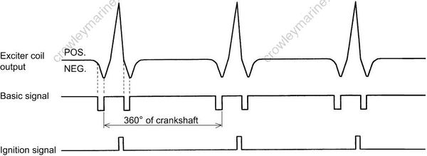
- This positive electrical energy is stored in the condenser for the ignition, while the negative electrical energy powers the control circuit and the basic signal for the ignition timing.
- The CPU calculates ignition timing based on the basic signal and sends the ignition signal to the SCR.
- When the SCR receives the ignition signal, it turns ON and the electric charge stored in the condenser is released to the primary ignition coil.
- A high surge of voltage in the secondary ignition coil then generates a spark.
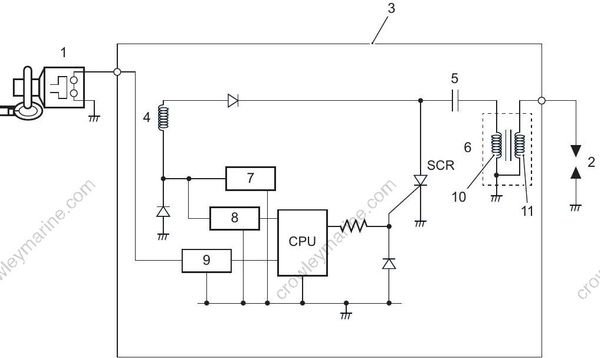
1.Emergency and engine stop switch
2.Spark plug
3.Igniter unit
4.Exciter coil
5.Condenser
6.Ignition coil
7.Power source circuit
8.Basic signal circuit
9.Stop signal circuit
10.Primary coil side
11.Secondary coil side
Ignition signal chart
Ignition Control Description
The coil’s negative output side produces the signal that the ECM uses to calculate ignition timing and engine speed, which the ECM then sends to the SCR.
Ignition specification
| Ignition type | Digital CDI |
|---|---|
| Advance | Electronic microcomputer control |
| Ignition timing | BTDC 0° – BTDC 28° |
Ignition Timing Control Mode
- When cranking
The ignition timing is approximately BTDC 5° at 600 r/min. - When operating (normal operation)
The ignition timing varies in the range of BTDC 0° – BTDC 28° according to the engine operating condition.
Over-Revolution Limiting System
The igniter unit incorporates an over-revolution limiter which limits maximum engine speed.
If the over-revolution limiter activates, the motor will exhibit a rough running condition.
Over revolution limiter
6000 r/min
Component Location
Ignition System Components Location
Refer to “Wiring Harness Routing Diagram” in Section 4A (Page 4A-4).
Diagnostic Information and Procedures
Ignition System Symptom Diagnosis
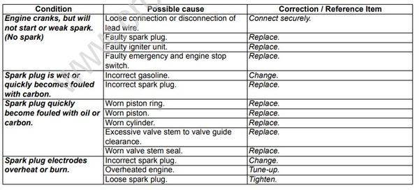
Ignition System Troubleshooting
Perform the following ignition system tests when the engine is hard to start in order to determine if the cause is in the ignition or another system.
Step 1
Check the ignition system lead wire for poor connections.
Is there connection in the ignition system lead wire?
Yes Go to step 2.
No Poor connection of lead wire.
Step 2
Check spark condition.
Is result OK?
Yes Go to step 8.
No No or weak sparks. Go to step 3.
Step 3
Check if the spark plug is in good condition.
Is result OK?
Yes Go to step 4.
No Replace spark plug with a new one.
Step 4
- Disconnect the emergency and engine stop switch lead wire.
- Check spark condition at engine cranking.
Is result OK?
Yes Check and/or replace emergency and engine stop switch.
No Go to step 5.
Step 5
Check the air gap between the igniter unit core and the flywheel.
Refer to “Igniter Unit Removal and Installation” (Page 1H-4).
Is result OK?
Yes Go to step 6.
No Adjust the air gap.
Step 6
Check igniter unit resistance.
Refer to “Igniter Unit Inspection” (Page 1H-5).
Is result OK?
Yes Go to step 7.
No Faulty igniter unit.
Step 7
Check the spark plug cap for any evidence of the high-tension leak.
Check spark plug cap resistance.
Refer to “Spark Plug Cap Inspection” (Page 1H-5).
Are result OK?
Yes Substitute a known-good igniter unit and recheck.
No Faulty spark plug cap.
Step 8
Check the ignition timing by using timing light.
Refer to “Ignition Timing Inspection” (Page 1H-6)
Is result OK?
Yes System is in good condition.
No Faulty igniter unit.
Service Instructions
Spark Plug Removal and Installation
Refer to “Spark Plug Removal and Installation” in Section 0B (Page 0B-8).
Spark Plug Inspection
Refer to “Spark Plug Inspection and Cleaning” in Section 0B (Page 0B-8).
Igniter Unit Removal and Installation
Removal
1) Remove the fuel tank.
Refer to “Fuel Tank Removal and Installation” in Section 1G (Page 1G-19).
2) Remove the fuel tank plate.
Refer to “Fuel Tank Removal and Installation” in Section 1G (Page 1G-19).
3) Remove the recoil starter.
Refer to “Recoil Starter Removal and Installation” in Section 1J (Page 1J-3).
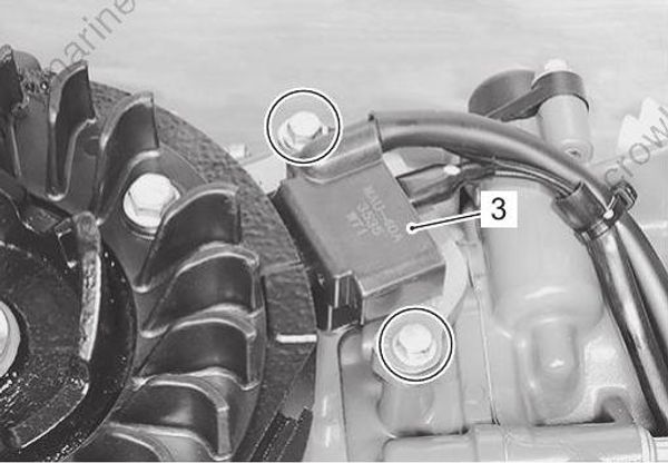
4) Disconnect the lead wire of emergency and engine stop switch (1) and cut the cable ties.
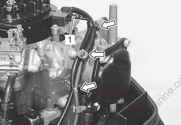
5) Remove the bolts (2) and igniter unit (3).
Installation
Installation is in the reverse order of removal with special attention to the following steps.
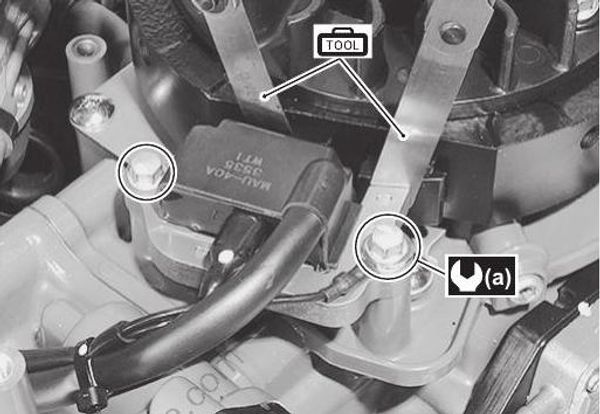
- Install the igniter unit with an air gap of 0.5 mm between the both core ends and the flywheel. Check the gaps at the reluctor bar (magnet) of the flywheel as shown in the figure.
Special tool : 09900–20803 (Thickness gauge)
Igniter unit air gap “a” : 0.5 mm (0.02 in.)
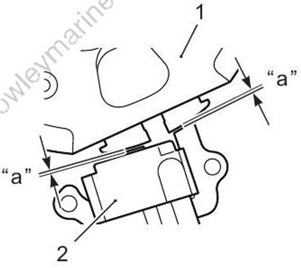
1.Flywheel
2.Igniter unit
“a”:0.5 mm (0.02 in.)
- Tighten the igniter unit mounting bolts with stop switch GND terminal to the specified torque.
Tightening torque
Igniter unit mounting bolt (a): 10 N·m (1.0 kgf-m, 7.0 lbf-ft)
- Connect the lead wire of emergency and stop switch to igniter unit securely.
- Secure the lead wire of emergency and stop switch with the cable ties.
- Check to ensure that all removed parts are back in original position.
- Check wire routing.
Refer to “Wiring Harness Routing Diagram” in Section 4A (Page 4A-4).
Igniter Unit Inspection
Special tool
(A): 09900–25008 (Multi circuit tester set)
Tester knob indication
Resistance (Ω)
Primary coil side
It is not possible to use resistance measurements to check for defects in the primary coil, because the primary coil side terminal is connected to the ignition circuit inside the igniter unit.
Secondary coil side
1) Remove the fuel tank.
Refer to “Fuel Tank Removal and Installation” in Section 1G (Page 1G-19).
2) Remove the fuel tank plate.
Refer to “Fuel Tank Removal and Installation” in Section 1G (Page 1G-19).
3) Remove the recoil starter.
Refer to “Recoil Starter Removal and Installation” in Section 1J (Page 1J-3).
4) Remove the spark plug cap from the high-tension cord.
5) Connect the tester probe between the high-tension cord and core as shown.
Secondary coil resistance
Standard: 2.0 – 3.0 kΩ
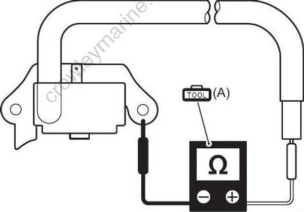
6) If measurement is out of specification, replace the igniter unit.
7) Install the recoil starter.
Refer to “Recoil Starter Removal and Installation” in Section 1J (Page 1J-3).
8) Install the fuel tank.
Refer to “Fuel Tank Removal and Installation” in Section 1G (Page 1G-19).
Spark Plug Cap Inspection
Measure the spark plug cap resistance in the following procedure.
Special tool
(A): 09900–25008 (Multi circuit tester set)
Tester knob indication
Resistance (Ω)
1) Remove the spark plug cap from high-tension cord.
2) Connect the tester probe to spark plug cap as shown.
Spark plug cap resistance
Standard: 4 – 6 kΩ
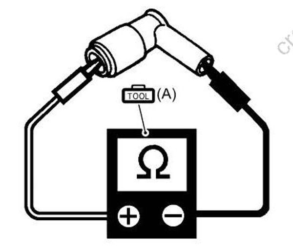
3) If measurement is out of specification, replace the spark plug cap.
4) Connect the spark plug cap to high-tension cord.
Emergency and Engine Stop Switch Inspection
1) Disconnect the emergency and engine stop switch lead wire.
2) Check the continuity / infinity between the wiring leads under the condition shown below.
Special tool
(A): 09900–25008 (Multi circuit tester set)
Tester knob indication
Continuity
| Tester probe connection Red (+) | Tester probe connection Black (–) | Tester indicates | |
|---|---|---|---|
| Lock plate installed | B | B | Infinity |
| Lock plate removed | B | B | Continuity |
| Lock plate installed and stop button depressed | B | B | Continuity |
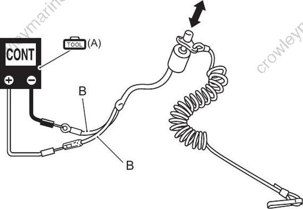
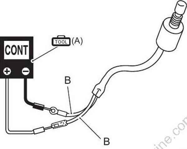
3) If out of specification, replace the switch.
Ignition Timing Inspection
Before checking the ignition timing, make sure idle speed is adjusted within specification.
1) Start the engine and allow to warm up.
2) Attach the timing light cord to the igniter unit high tension cord.
Special tool
(A): 09930–76311 (Timing light)
: 09900–26006 (Engine tachometer)
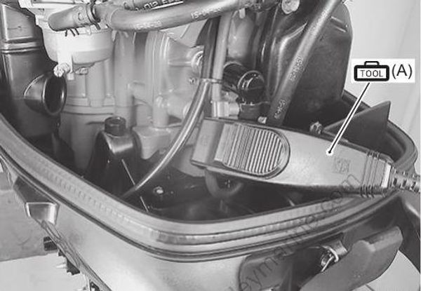
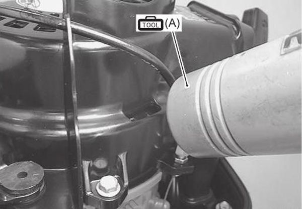
3) Check the ignition timing while operating the engine in neutral gear.
Ignition timing
Approx. BTDC 0° at 1300 r/min.
Approx. BTDC 28° at 3500 r/min.
