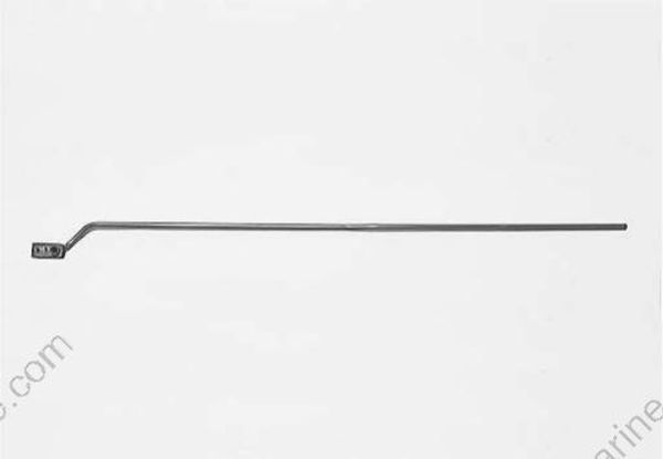
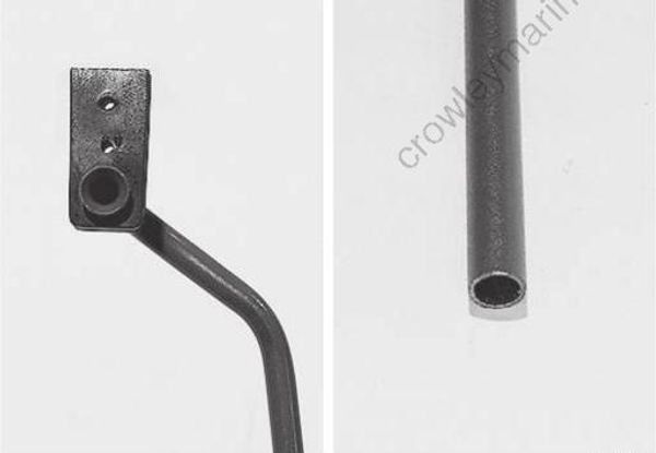
Step 1: Precautions
Precaution for Housing and Bracket
When dismantling housing and bracket, inspect mountings and bolts for damage and wear. Replace if necessary.
Step 2: Service Instructions
Engine Lower Cover Components
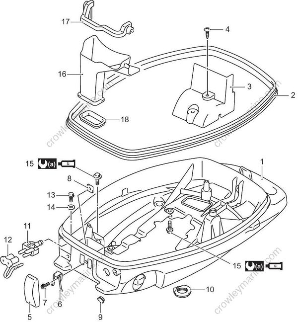
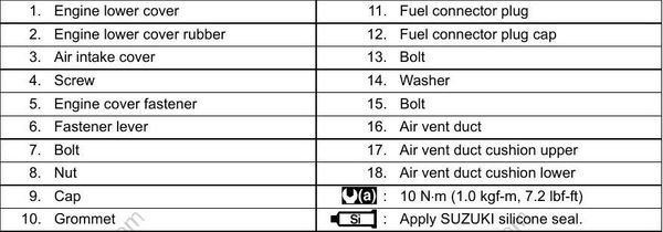
Step 3: Engine Lower Cover Removal and Installation
Removal
1) Remove the power unit.
Refer to “Power Unit Removal and Installation” in Section 1D (Page 1D-4).
2) Remove the four bolts securing the engine lower cover, then remove the cover.
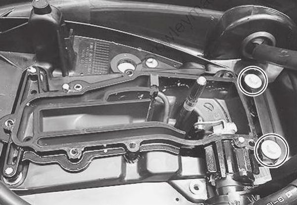
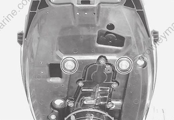
Installation
Installation is in the reverse order of removal with special attention to the following.
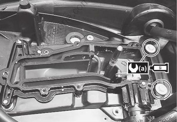
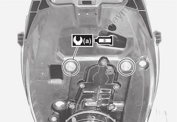
- Apply Suzuki silicone seal to the engine lower cover mounting bolts, then tighten the bolts to the specified torque.
Tightening torque
Engine lower cover mounting bolt (a): 10 N·m (1.0 kgf⋅m, 7.2 lbf⋅ft)
: Sealant 93691–80030 (SUZUKI Silicone Seal (100 g))
Step 4: Tiller Handle Removal and Installation
Removal
1) Remove the fuel tank.
Refer to “Fuel Tank Removal and Installation” in Section 1G (Page 1G-19).
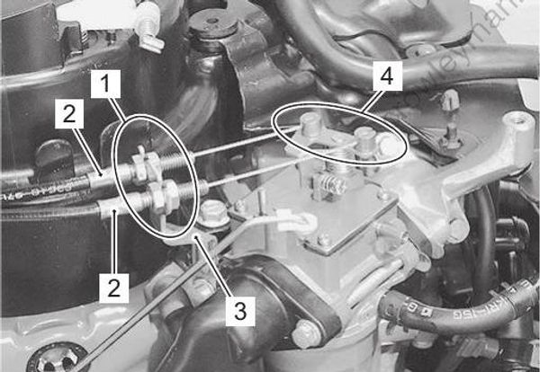
2) Loosen the throttle control cable lock nuts (1), then remove the throttle control cables (2) from the throttle control cable bracket (3) and the linkage (4).
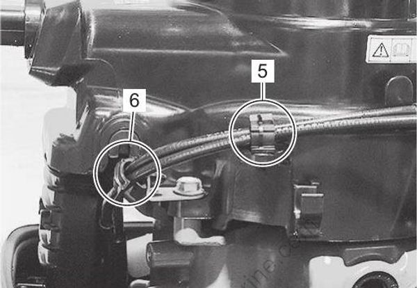
3) Remove the throttle control cables from the clamp (5) and the clamp (6).
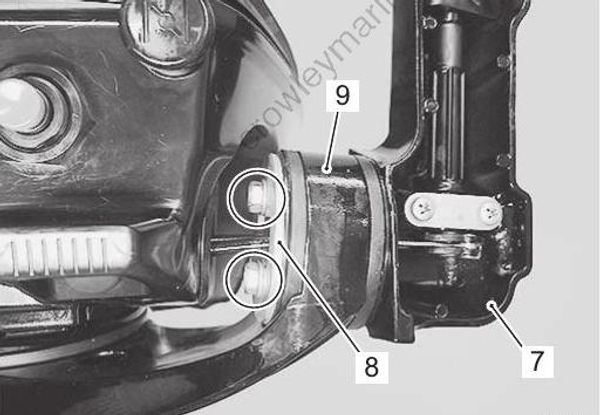
4) Remove the two bolts securing the tiller handle assembly (7), then remove the tiller handle assembly and the stopper (8) from the steering bracket (9).
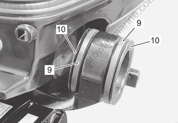
5) Remove the mounts (9) and the bushings (10) from the steering bracket.
Installation
Installation is in the reverse order of removal with special attention to the following steps.
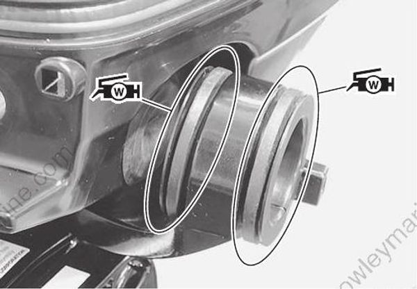
Mounts and Bushings
Apply water resistant grease to inside and outside surface of the bushings and the mounts.
Install the mounts and the bushings to the steering bracket.
: Grease 99000–25350 (SUZUKI Water Resistant Grease EP2 (250 g))
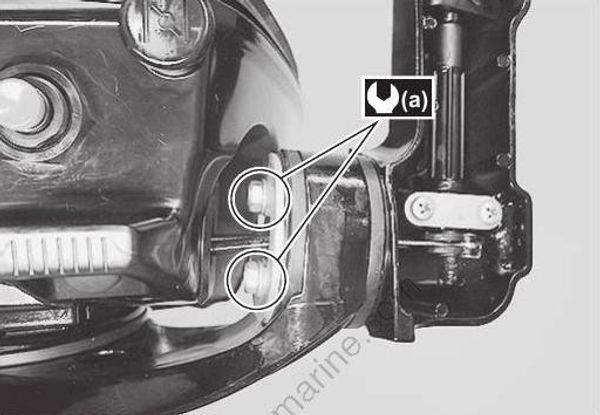
Tiller Handle Assembly
- Install the tiller handle assembly and the stopper to the steering bracket, then tighten the tiller handle mounting bolt to the specified torque.
Tightening torque
Tiller handle mounting bolt (a): 10 N·m (1.0 kgf⋅m, 7.2 lbf⋅ft)
- Install the throttle cable protector to the throttle control cables as shown in the figure.
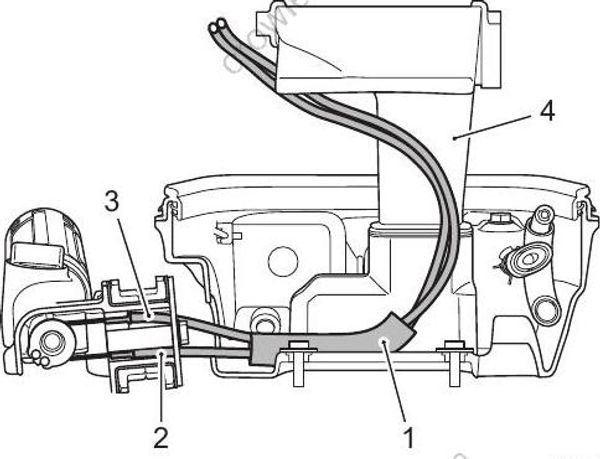
1.Throttle cable protector
2.For open throttle
3.For close throttle
4.Air vent duct
- Make sure that the throttle control inner and outer cables fit in the tiller handle body as shown in the figure.
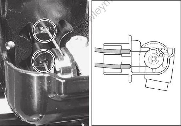
- Install the throttle control cables to the throttle control cable bracket and the linkage.
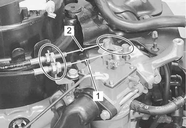
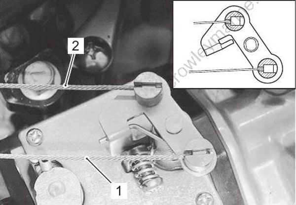
- For open throttle
- For close throttle
- Adjust of throttle control cables.
Refer to “Throttle Control Cable Installation and Adjustment” (Page 2A-6).
Final assembly check
- Perform the following final assembly checks to ensure proper and safe operation of the repaired unit.
– All parts removed have been returned to their original positions.
Step 5: Throttle Control Cable Installation and Adjustment
1) Fully close the throttle control grip.
2) Turn the throttle stop screw (1) counterclockwise until the screw dose not touch the stopper plate (2).
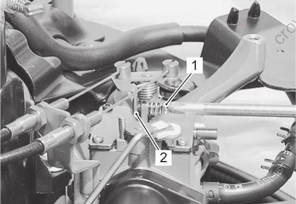
3) Insert the throttle control inner cable (3) and (4) into the linkage hole.
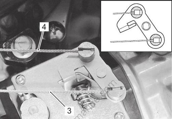
- For open throttle
- For close throttle
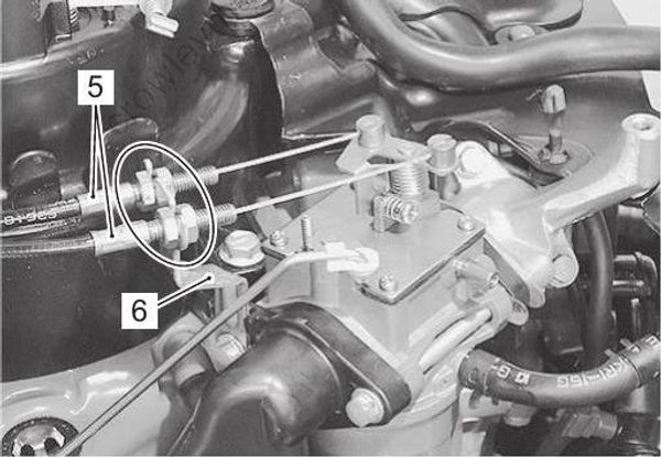
4) Install the throttle control outer cables (5) to the throttle control cable bracket (6).
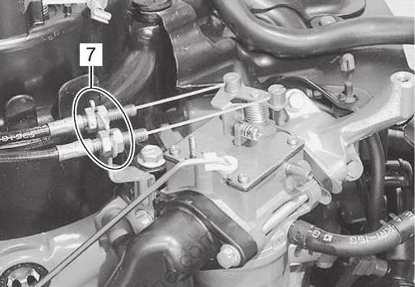
5) Turn the lock nuts (7) in appropriate direction to install inner cable with no sag.
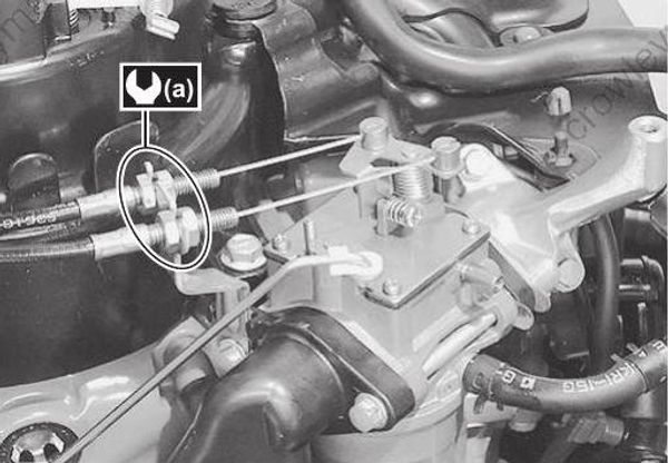
6) Tighten the lock nuts to secure the throttle cable to the throttle control cable bracket.
Tightening torque
Throttle cable adjusting nut (a): 4 N·m (0.4 kgfm, 3.0 lbf⋅ft)
7) Check that the throttle control is smoothly operated from the full closed position to the full opened position.
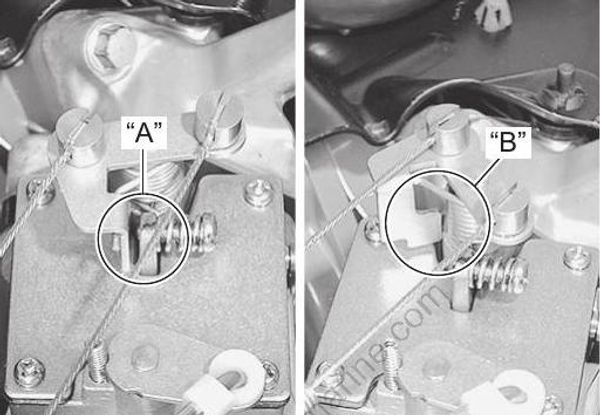
“A”: Full close position
“B”: Full open position
Step 6: Tiller Handle Components
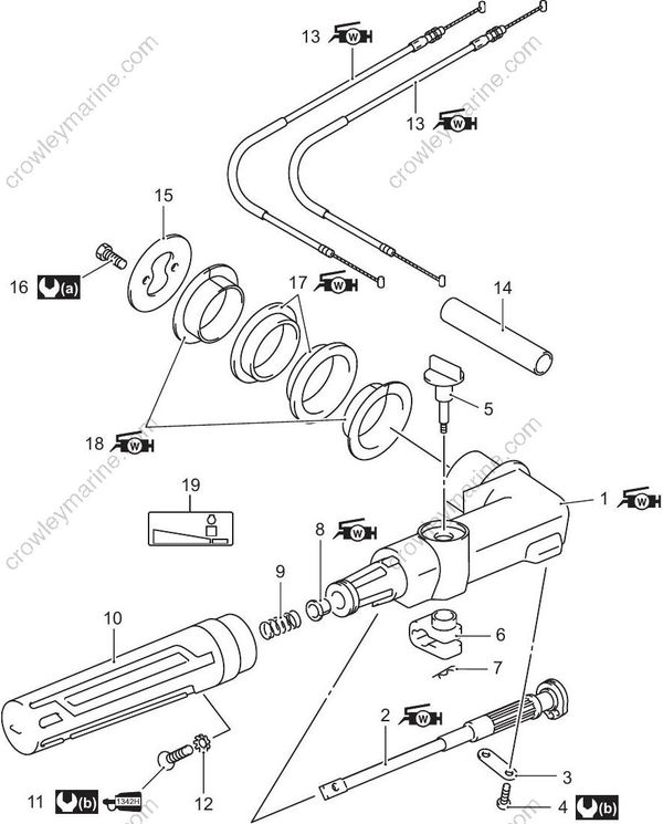
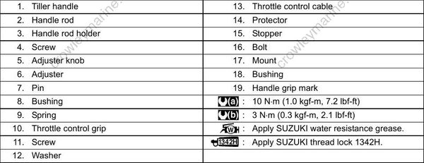
Step 7: Tiller Handle Disassembly and Assembly
Disassembly
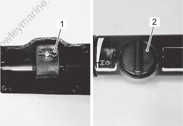
1) Remove the pin (1), then loosen and remove the throttle adjuster knob (2).
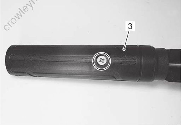
2) Remove the screw securing the throttle control grip (3), then remove the throttle control grip.
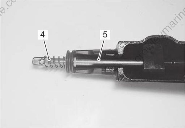
3) Remove the spring (4) from the handle rod (5).
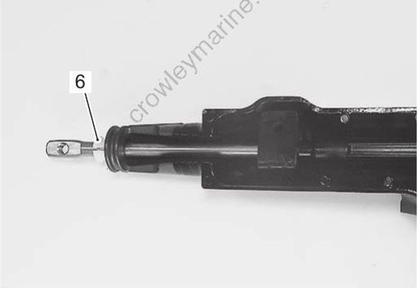
4) Remove the handle rod bushing (6).
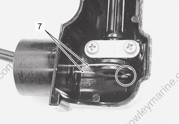
5) Remove the throttle control cables (7) from the drum of the handle rod.
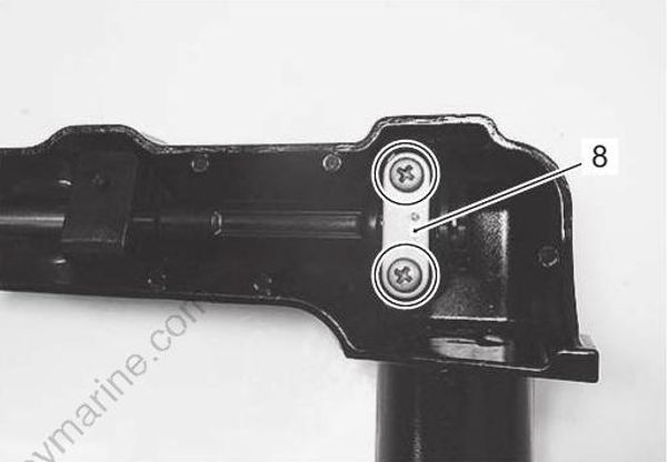
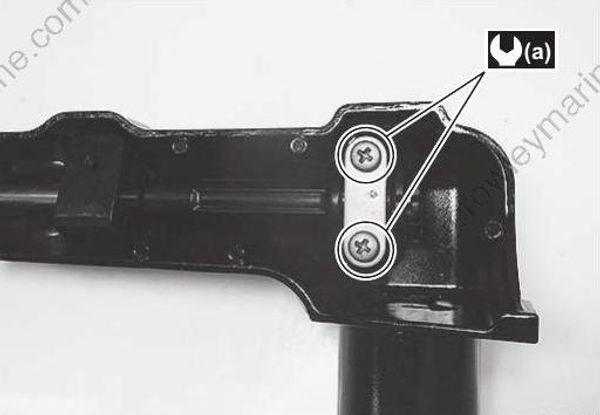
6) Remove the two screws securing the handle rod holder (8), then remove the handle rod holder.
7) Remove the handle rod (9) from the tiller handle body.
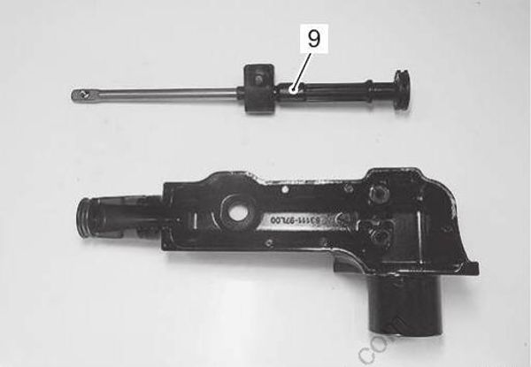
8) Remove the throttle adjuster (10) from the handle rod.
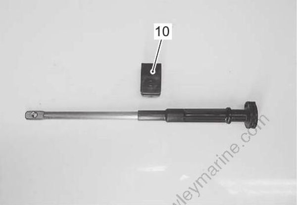
Assembly
Assembly is in the reverse order of disassembly with special attention to the following steps.
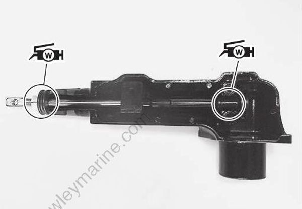
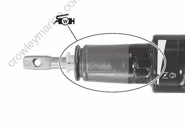
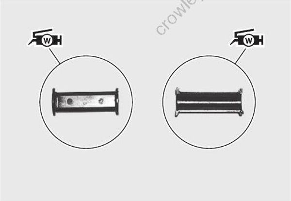
- Apply water resistant grease to the handle rod, the handle rod bushing and the tiller handle body as shown in the figure.
: Grease 99000–25350 (SUZUKI Water Resistant Grease EP2 (250 g))
- Tighten the handle rod holder screw to the specified torque.
Tightening torque
Handle rod holder screw (a): 3 N·m (0.3 kgf-m, 2.1 lbf⋅ft)
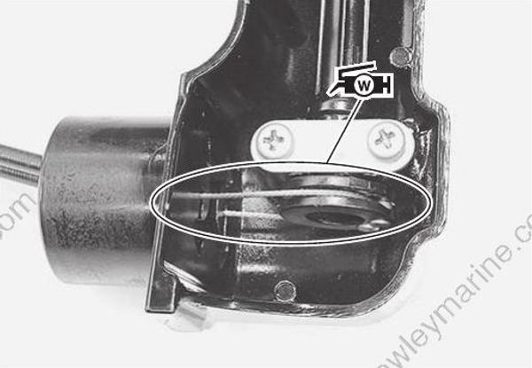
- Make sure that the throttle control inner cables fit in the groove on the drum of the handle rod.
Apply water resistant grease to the inner cables.
: Grease 99000–25350 (SUZUKI Water Resistant Grease EP2 (250 g))
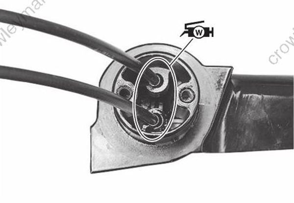
- Make sure that the throttle control outer cables fit in the tiller handle body as shown in the figure.
Apply water resistant grease to the outer cables when install them to the tiller handle body.
: Grease 99000–25350 (SUZUKI Water Resistant Grease EP2 (250 g))
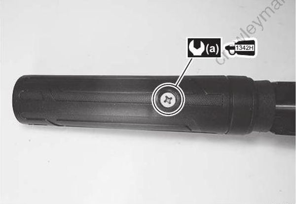
- Tighten the throttle control grip screw, pre-coated with thread lock, to the specified torque.
Tightening torque
Throttle control grip screw (a): 3 N·m (0.3 kgf⋅m, 2.1 lbf⋅ft)
: Thread lock cement 99000–32160 (SUZUKI Thread Lock 1342H (50g))
Step 8: Clamp / Swivel / Steering Brackets Components
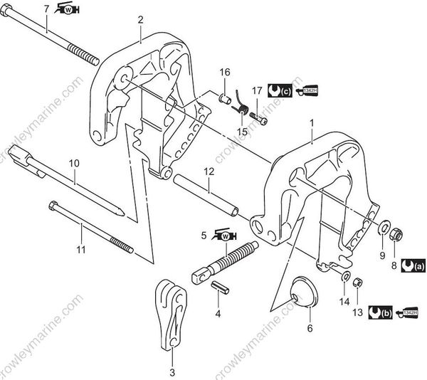
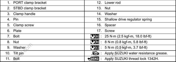
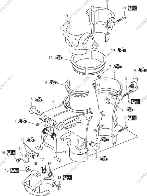
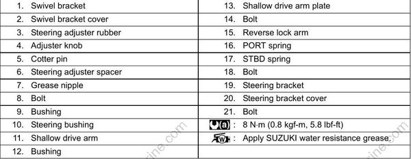
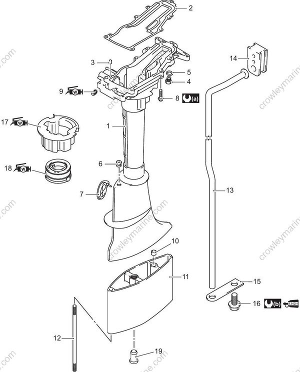
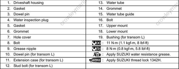
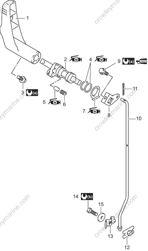
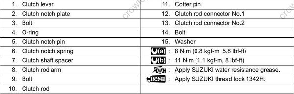
Step 9: Clamp / Swivel / Steering Bracket / Driveshaft Housing Disassembly
- Remove the power unit.
Refer to “Power Unit Removal and Installation” in Section 1D (Page 1D-4).
- Remove the lower unit.
Refer to “Lower Unit Removal and Installation” in Section 3A (Page 3A-5).
- Remove the engine lower cover.
Refer to “Engine Lower Cover Removal and Installation” (Page 2A-3).
- Remove the tiller handle.
Refer to “Tiller Handle Removal and Installation” (Page 2A-4).
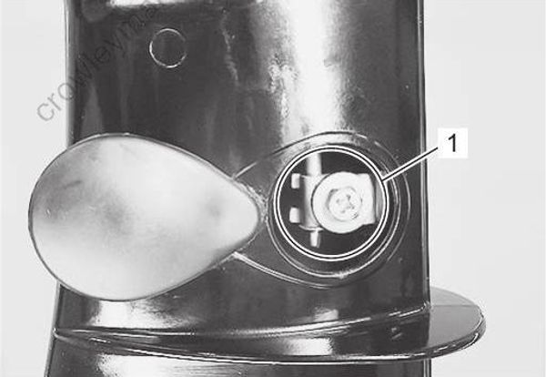
1) Remove the bolt and the clutch rod connector (1).
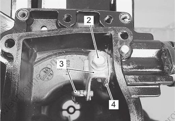
2) Remove the bolt (2), clutch rod/arm (3) and spacer (4) from the clutch notch plate shaft.
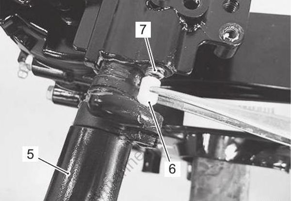
3) Remove the clutch lever (5) with the clutch notch plate, the notch pin (6) and the spring (7) from the driveshaft housing.
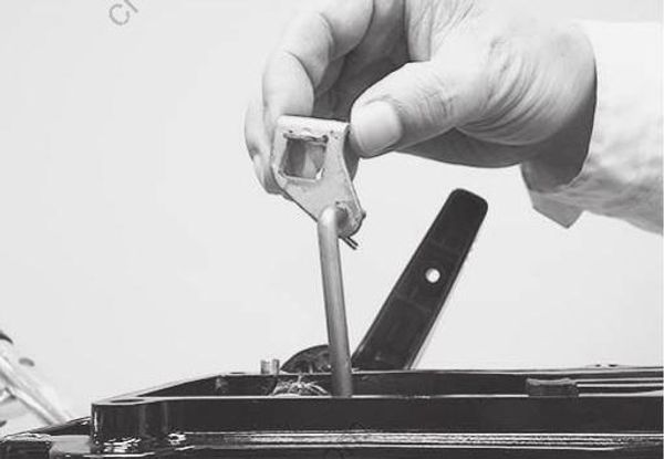
4) Remove the clutch rod/arm.
5) Remove the water tube and grommet (8).
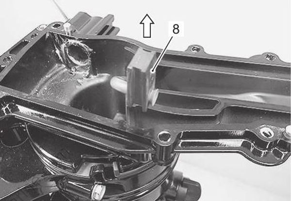
6) Remove the two bolts securing the reverse lock arm (9).
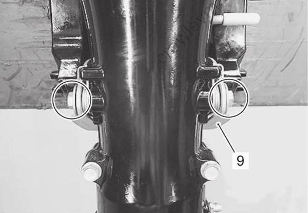
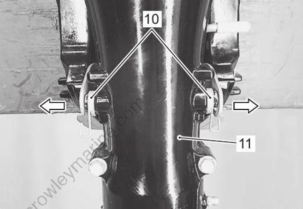
7) Slightly expand the reverse lock arm, then remove the reverse lock arm and the springs (10) from the swivel bracket cover (11).
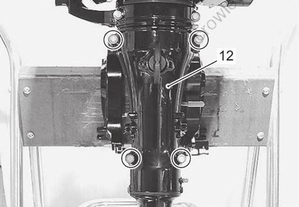
8) Remove the four bolts securing the swivel bracket cover (12), then remove the cover and the steering adjuster rubber (13).
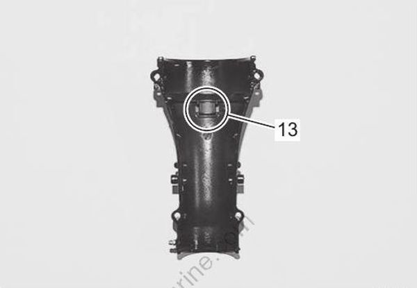
9) Remove the driveshaft housing / steering bracket assembly (14) and the bushings (15) from the swivel bracket (16).
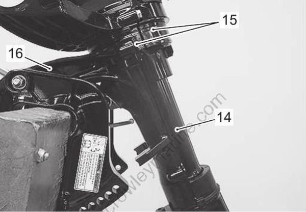
10) Remove the steering adjuster spacer (17) from the swivel bracket.
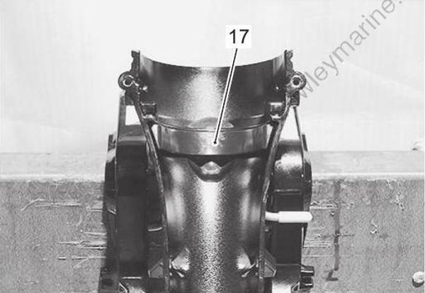
11) Remove the two bolts securing the steering bracket cover (18).
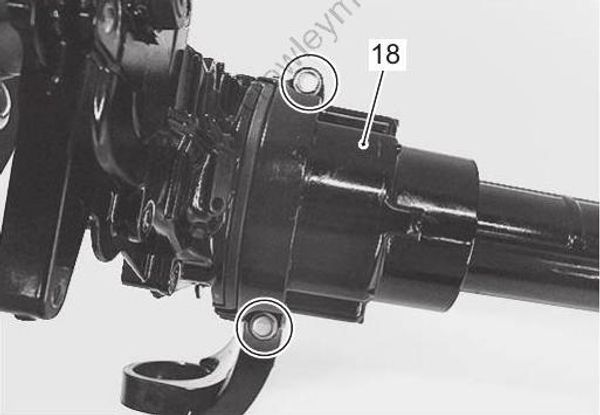
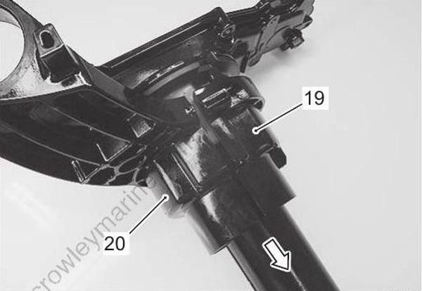
12) Slide the steering bracket cover (19) downward, then remove the cover.
Slide the steering bracket (20) downward, then remove the bracket.
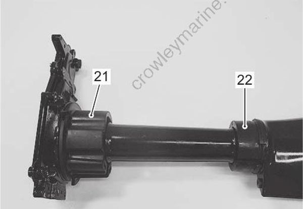
13) Remove the upper mount (21) and the lower mount (22).
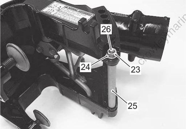
14) Remove the nut (23), the washer (24), the lower rod (25) and the through bolt (26).
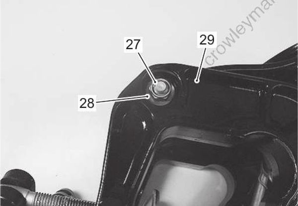
15) Remove the upper nut (27) and the washer (28), then remove the PORT clamp bracket (29).
16) Remove the upper bolt (30) and the STBD clamp bracket (31).
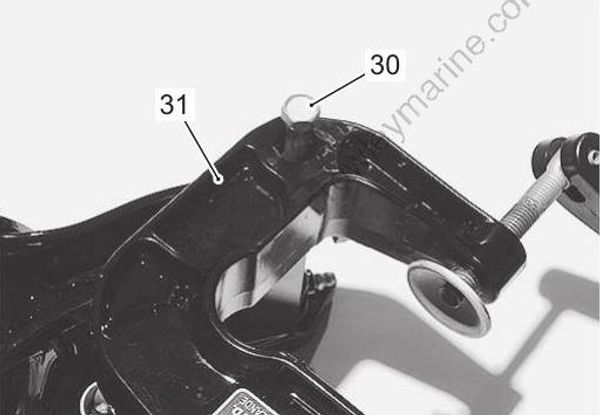
17) Remove the bushings (32) from the swivel bracket.
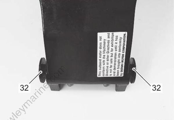
18) Remove the two bolts securing the shallow drive arm plate (33), then remove the plate.
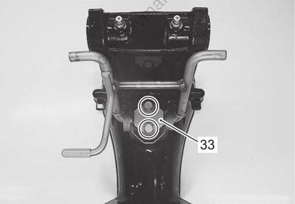
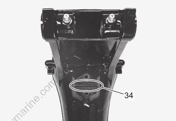
19) Remove the bushings (34) and the shallow drive arm (35).
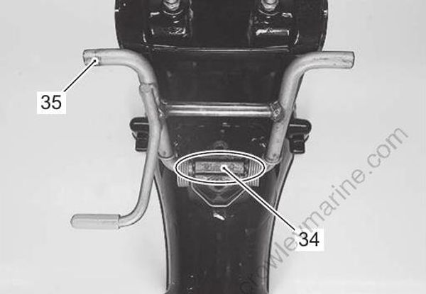
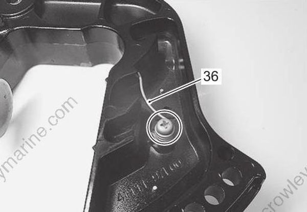
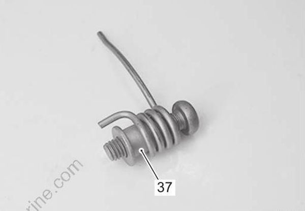
20) Remove the screw securing the shallow drive regulator spring (36), then remove the spring and the spacer (37) from the STBD clamp bracket.
Step 10: Clamp / Swivel / Steering Bracket / Driveshaft Housing Assembly
Assembly is in the reverse order of disassembly with special attention to the following steps.
Shallow Drive Regulator
- Assemble the shallow drive regulator as shown in the figure.
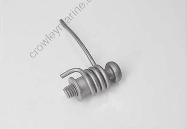
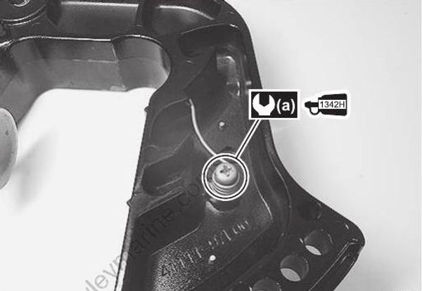
- Install the shallow drive regulator to the STBD clamp bracket, then tighten the screw, pre-coated with thread lock, to the specified torque.
Tightening torque
Regulator spring screw (a): 5 N·m (0.5 kgf⋅m, 3.7 lbf⋅ft)
: Thread lock cement 99000–32160 (SUZUKI Thread Lock 1342H (50g))
Shallow Drive Arm
- Apply water resistant grease to inside/outside surface of the bushings.
: Grease 99000–25350 (SUZUKI Water Resistant Grease EP2 (250 g))
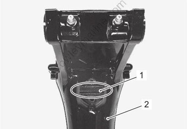
- Install the bushing (1) to the swivel bracket (2).
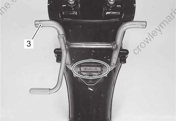
- Install the shallow drive arm (3) and the bushing to the swivel bracket.
- Install the shallow drive arm plate (5), then tighten the bolts (6) to the specified torque.
Tightening torque
Shallow drive arm plate bolt (a): 8 N·m (0.8 kgf⋅m, 5.8 lbf⋅ft)
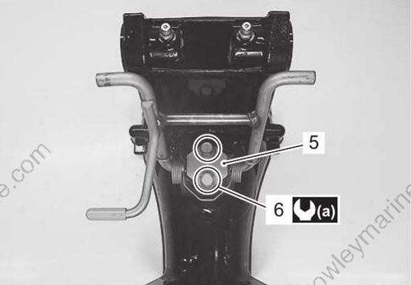
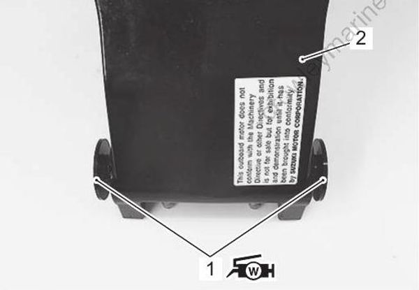
Clamp Bracket and Swivel Bracket
• Apply water resistant grease to the bushings (1), and install the bushings to the swivel bracket (2).
: Grease 99000–25350 (SUZUKI Water Resistant Grease EP2 (250 g))
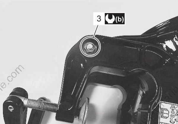
- Tighten the clamp bracket shaft nut (3) to the specified torque.
Tightening torque
Clamp bracket shaft nut (b): 25 N·m (2.5 kgf⋅m, 18.0 lbf⋅ft)
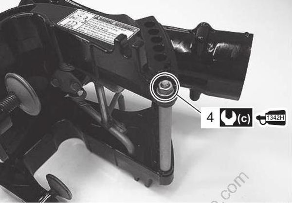
- Tighten the clamp bracket lower rod nut (4), pre-coated with thread lock, to the specified torque.
Tightening torque
Clamp bracket lower rod nut (c): 8 N·m (0.8 kgf⋅m, 5.8 lbf⋅ft)
**: Thread lock cement 99000–32160 (SUZUKI Thread Lock 1342H (50g))
Driveshaft Housing and Steering Bracket
Apply water resistant grease to inside/outside surface of the bushings.
Apply water resistant grease to inside/outside surface of the mounts.
: Grease 99000–25350 (SUZUKI Water Resistant Grease EP2 (250 g))
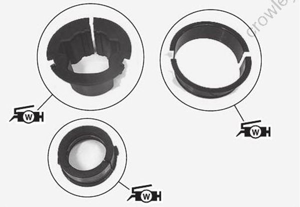
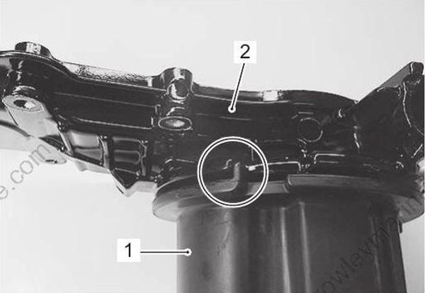
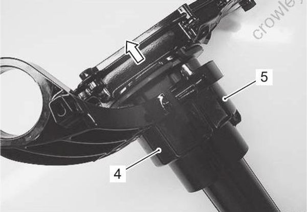
- Install the upper mount (1) to the driveshaft housing (2) as shown in the figure.
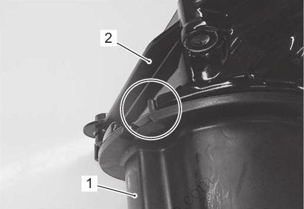
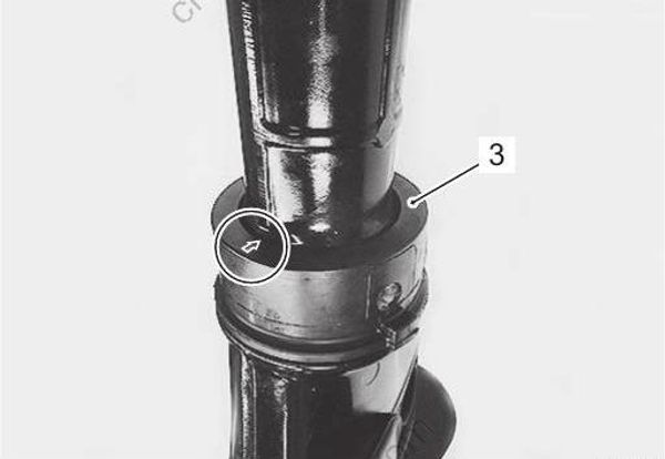
- Install the lower mount (3) to the driveshaft housing, then align the allow mark on the lower mount to the driveshaft housing as shown in the figure.
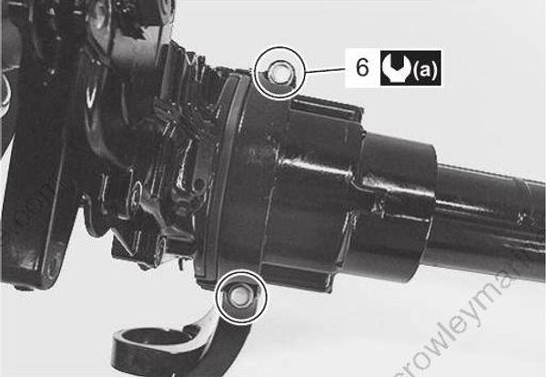
- Install the steering bracket (4) and steering bracket cover (5), then tighten the bolts (6) to the specified torque.
Tightening torque
Steering bracket cover bolt (a): 8 N·m (0.8 kgf⋅m, 5.8 lbf⋅ft)
- Install the bushing (7) and the steering adjuster spacer (8) to the swivel bracket (9).
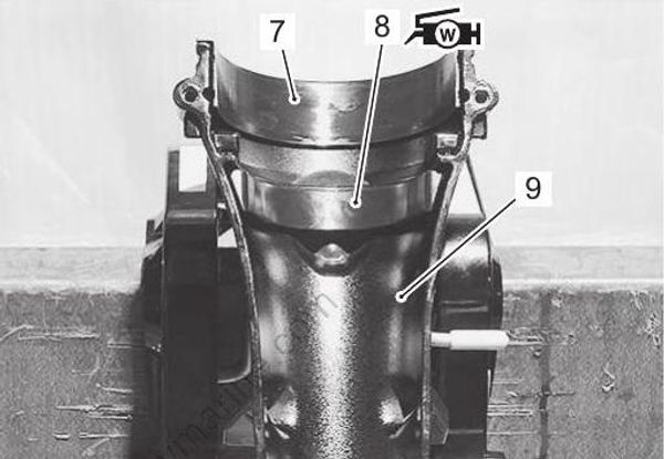
- Install the driveshaft housing/steering bracket assembly (10) and the bushing (11) to the swivel bracket.
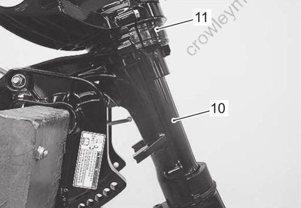
- Apply water resistant grease to the adjuster knob thread.
: Grease 99000–25350 (SUZUKI Water Resistant Grease EP2 (250 g))
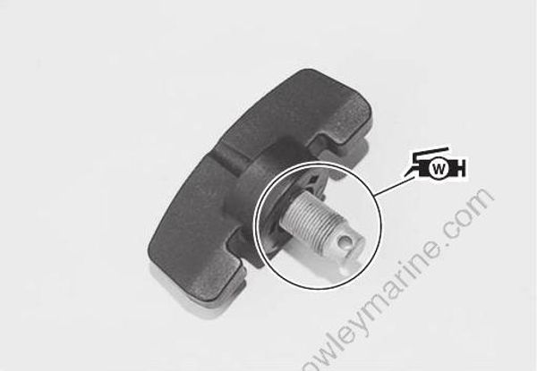
- Apply water resistant grease to the steering adjuster rubber (12), then install the steering adjuster rubber to the swivel bracket cover (13).
:Grease 99000–25350 (SUZUKI Water Resistant Grease EP2 (250 g))
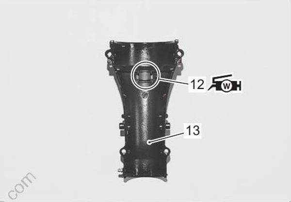
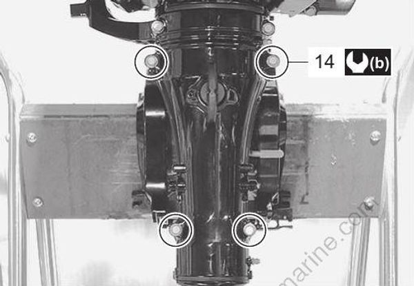
- Install the swivel bracket cover to the swivel bracket, then tighten the bolts (14) to the specified torque.
Tightening torque
Swivel bracket cover bolt (b): 8 N·m (0.8 kgf⋅m, 5.8 lbf⋅ft)
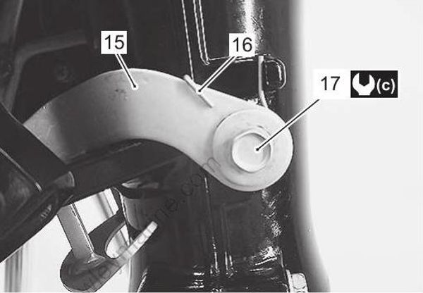
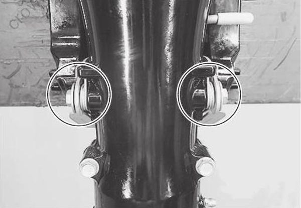
- Install the reverse lock arm (15) and the springs (16), then tighten the bolts (17) to the specified torque.
Tightening torque
Reverse lock arm bolt (c): 8 N·m (0.8 kgf⋅m, 5.8 lbf⋅ft)
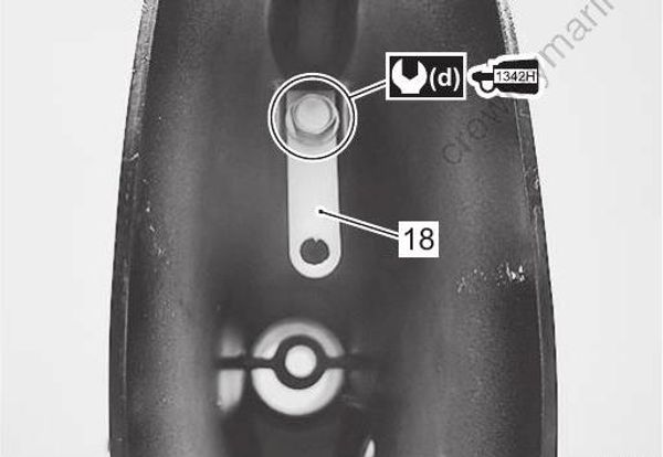
- Install the water tube guide (18), then tighten the bolt, pre-coated with thread lock, to the specified torque.
Tightening torque
Water tube guide bolt (d): 8 N·m (0.8 kgf⋅m, 5.8 lbf⋅ft)
: Thread lock cement 99000–32160 (SUZUKI Thread Lock 1342H (50g))
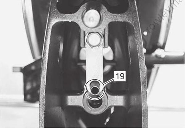
- Install the water tube (19) through the water tube guide.
Clutch Lever
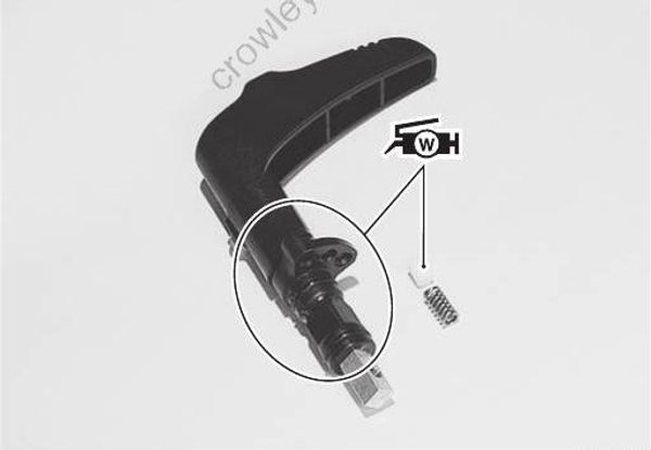
- If excessive wear or other damage is found on the notch pin or clutch notch plate, replace.
- Apply water resistant grease to the notch pin, the notch holes and a new O-rings on the clutch notch plate.
: Grease 99000–25350 (SUZUKI Water Resistant Grease EP2 (250 g))
- Tighten the clutch rod arm bolt, pre-coated with thread lock, to the specified torque.
Tightening torque
Clutch rod arm bolt (a): 8 N·m (0.8 kgf⋅m, 5.8 lbf⋅ft)
: Thread lock cement 99000–32160 (SUZUKI Thread Lock 1342H (50g))
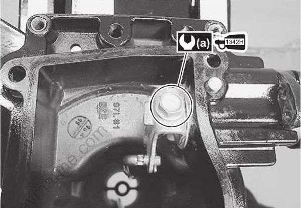
Lubrication
After completing reassembly of the mid unit, apply grease through each grease nipples.
Refer to “Lubrication Point” in Section 0B (Page 0B-3).
: Grease 99000–25350 (SUZUKI Water Resistant Grease EP2 (250 g))
Step 11: Clamp / Swivel / Steering Brackets Related Components Inspection
Refer to “Clamp / Swivel / Steering Bracket / Driveshaft Housing Disassembly” (Page 2A-14) and “Clamp / Swivel / Steering Bracket / Driveshaft Housing Assembly” (Page 2A-17).
If any component is found to be excessively worn, cracked, defective or damaged in any way, it must be replaced.
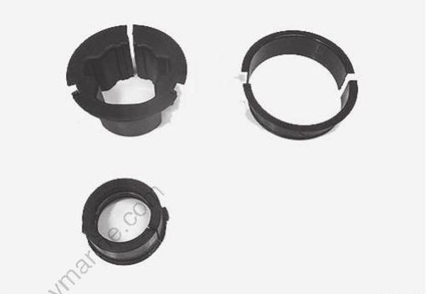
Mounts and Bushings
Check all mounts. If excessive wear or other damage is found, replace mount. If mount fit is loose when installing, replace mount.
Check all bushings. If excessive wear or other damage is found, replace bushing. If bushing fit is loose when installing, replace bushing.
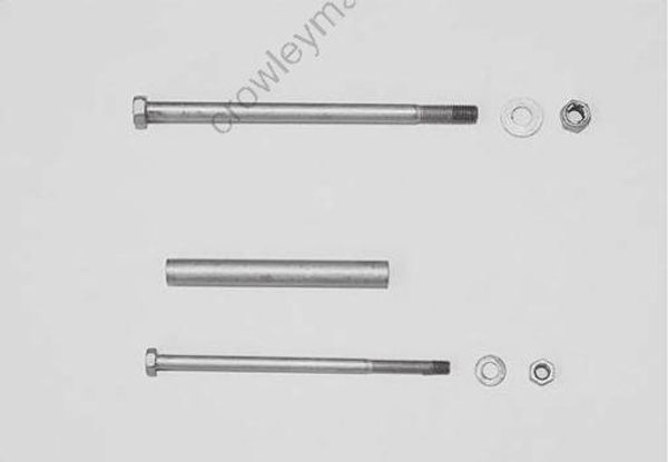
Clamp Bracket Shaft
Check clamp bracket shaft.
If clamp bracket shaft is bent or twisted, replace shaft(s).
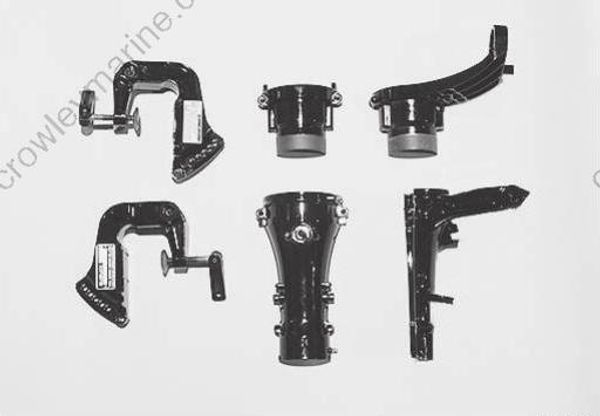
Bracket
Check clamp brackets, steering bracket and swivel bracket.
If cracks or other damage is found, replace bracket (s).
Driveshaft Housing
Inspect the driveshaft housing.
If crack or other damage is found, replace.
Water Tube / Water Tube Grommet
- Check water tube.
If a clog or obstruction is found, clean water tube.
If cracks, corrosion or other damage is found, replace water tube.
- Check water tube grommet.
If excessive wear or other damage is found, replace grommet.