

Removal
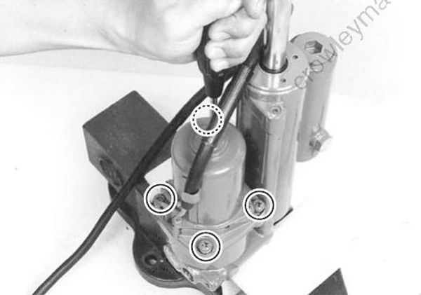
Remove the four (4) screws securing the PTT motor to the pump & reservoir.
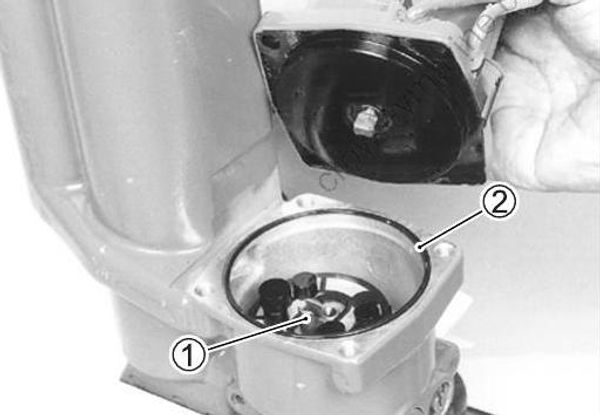
Detach the PTT motor from pump & reservoir.
Note the position of drive joint (1) and O-ring (2) and remove them.
PTT motor Disassembly
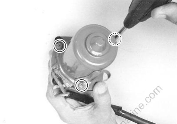
For correct assembly, scribe an alignment mark on the field case and brush holder.
Remove the three (3) screws securing the field case to the brush holder.
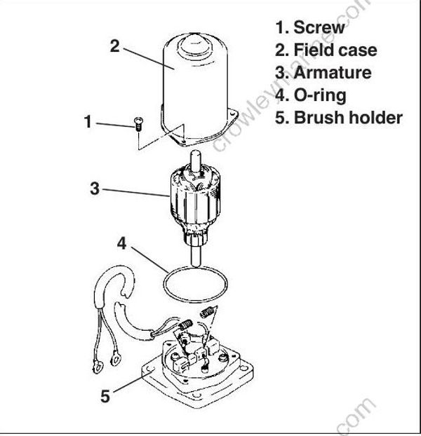
Using a soft face hammer, gently tap the field case from side to side to unseat it from the brush holder.
Slide the field case upward and away from the brush holder.
Note the position of the O-ring encircling the brush holder.
Slide the armature free of the brushes.
Inspection
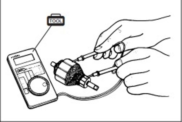
Armature and Commutator
Check for continuity between the commutator and the armature core / shaft.
Replace armature if continuity is indicated.
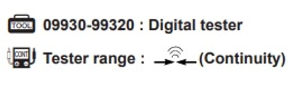
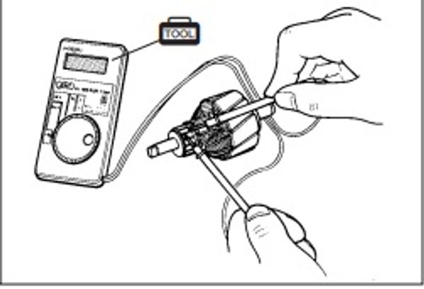
Check continuity between the adjacent commutator segments.
Replace armature if no continuity is indicated.
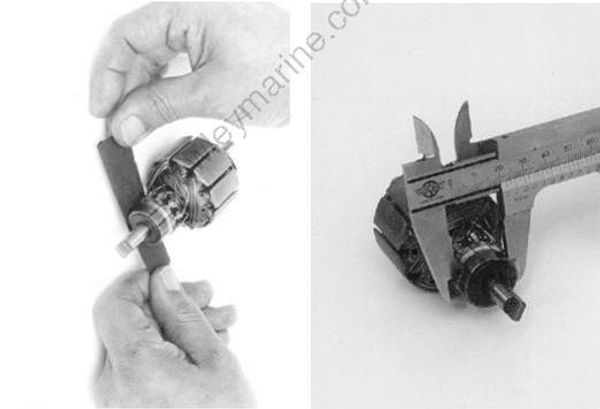
Inspect the commutator surface.
If surface is gummy or dirty, clean with 400 grade emery paper.
Measure commutator outside diameter.

Commutator outside diameter :
Standard 22 mm (0.87 in.)
Service limit 21 mm (0.83 in.)
If measurement exceeds service limit, replace armature.
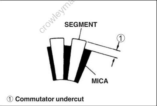
Ensure that the mica (insulator) between the segments is undercut to specified depth.
Commutator undercut :
Standard 0.5 – 0.8 mm (0.02 – 0.03 in.)
Service limit 0.2 mm (0.008 in.)
If undercut is less than service limit, cut to specified depth.
Remove all particles of mica and metal using compressed air.
Wear safety grasses when using compressed air.
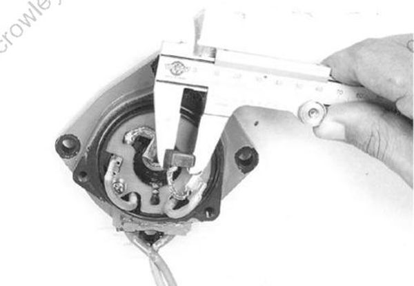
Brushes
Check the length of each brush.

Brush length :
Standard 9.8 mm (0.39 in.)
Service limit 4.8 mm (0.19 in.)
If brushes are worn down to the service limit, they must be replaced .
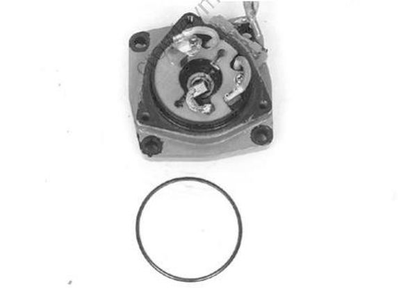
O-ring
Inspect the O-ring between the PTT motor and pump & reservoir. Replace if cuts, nicks or tears are found
Assembly
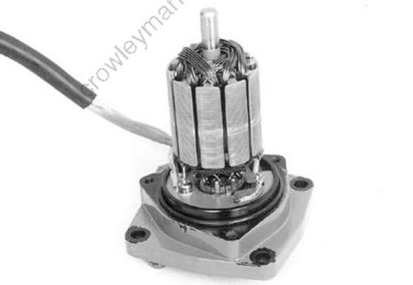
Assembly is reverse of disassembly with special attention to following steps.
When installing the armature, exercise care not to break the brushes.
When installing armature, exercise care to avoid breaking brushes.
PTT Motor Installation
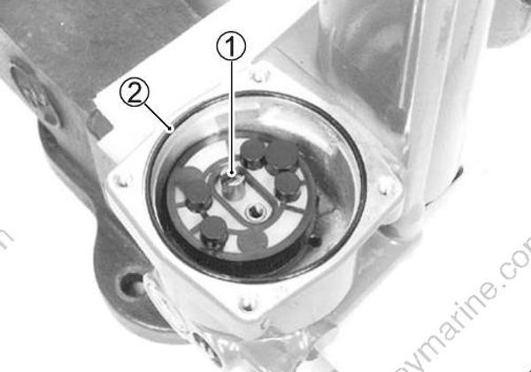
Installation is reverse of removal with special attention to following steps.
Ensure that the drive joint 1 is aligned and firmly inserted into the gear pump assembly.
Fit O-ring 2 to pump & reservoir
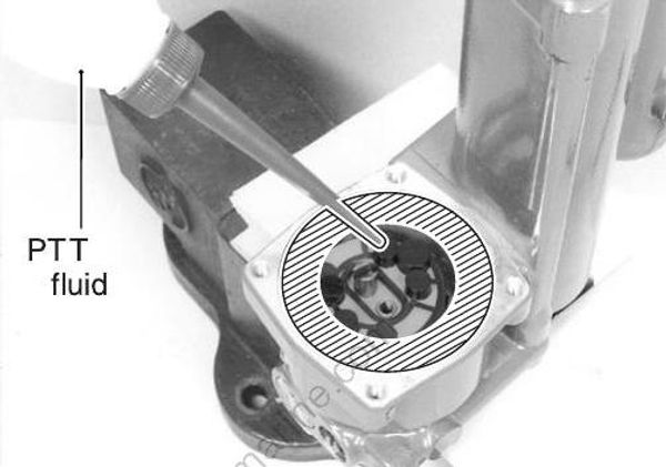
- Check the level of PTT fluid contained in the pump & reservoir. If level is low, add recommended PTT fluid until level with mating surface of PTT motor.
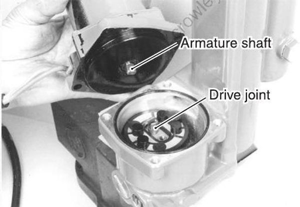
- Ensure that the faces of the PTT motor and pump unit are free of dirt or debris.
When attaching the PTT motor to the pump & reservoir, ensure that the tip of armature shaft fits firmly into the drive joint.
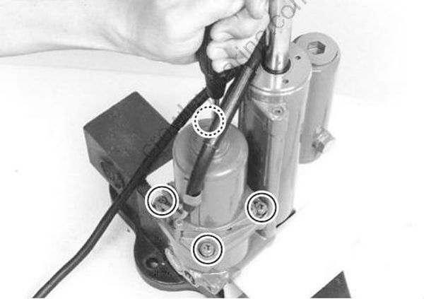
- Tighten the four (4) screws to specified torque.

