

ENGINE CONTROL SYSTEM
Main modifications from “K1” (‘01) model are as follows:
For more accurate control, ECM, CKP sensor, flywheel magneto etc. have been modified.
Ignition timing and fuel injection timing controls have been modified.
The total operating hours indication system has been modified.
An oil change reminder system has been added.
Self-diagnostic for fuel injector circuit has been added.
ENGINE CONTROL SYSTEM STRUCTURE
SYSTEM STRUCTURE
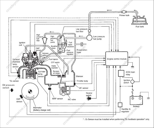
WIRING DIAGRAM FOR ENGINE CONTROL
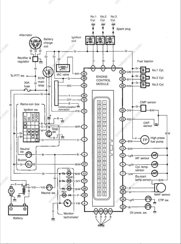
ECM CIRCUIT
| TERMINAL | WIRE COLOR | CIRCUIT |
|---|---|---|
| 1 | – | – |
| 2 | Bl/R | Emergency stop switch |
| 3 | O | Buzzer cancel |
| 4 | Y/B | Tachometer |
| 5 | Br | Neutral switch, Engine start signal |
| 6 | – | – |
| 7 | V/W | Ex-manifold temperature sensor |
| 8 | – | – |
| 9 | Lg/W | Cylinder temperature sensor |
| 10 | B | Ground for ECM |
| 11 | B/W | Ground for sensor |
| 12 | Bl/B | OIL lamp |
| 13 | P/B | Ground for ECM main relay |
| 14 | – | – |
| 15 | R/B | CKP sensor |
| 16 | O/Y | PC communication |
| 17 | G/Y | TEMP lamp |
| 18 | B/R | IAC valve solenoid (–) |
| 19 | – | – |
| 20 | B | Ground for power souce |
| 21 | – | – |
| 22 | G | No.3 Ignition (–) |
| TERMINAL | WIRE COLOR | CIRCUIT |
|---|---|---|
| 23 | Bl | Oil pressure switch |
| 24 | Lg/R | CTP switch |
| 25 | P | REV-LIMIT lamp |
| 26 | G/W | CHECK ENGINE lamp |
| 27 | Bl/W | Buzzer |
| 28 | – | – |
| 29 | W | MAP sensor |
| 30 | Gr | ECM power source |
| 31 | Lg/B | IAT sensor |
| 32 | B | Ground for ECM |
| 33 | O/G | CMP sensor |
| 34 | B/G | O2 feedback |
| 35 | R | Power source for MAP sensor |
| 36 | Y | PC communication |
| 37 | B/W | Fuel pump (–) |
| 38 | R/W | No.3 Fuel injector (–) |
| 39 | B/Y | No.2 Fuel injector (–) |
| 40 | O/B | No.1 Fuel injector (–) |
| 41 | – | – |
| 42 | B | Ground for power source |
| 43 | Bl | No.2 Ignition (– |
| 44 | O | No.1 Ignition (–) |
“WIRE COLOR” shows the wire color of engine wire harness side.
ECM TERMINAL LAYOUT / TEST CORD
Terminal layout on the ECM is the same as the “❉” marked terminal in the illustration of the 44-pin test cord (special tool P/N. 09930-89950) below.
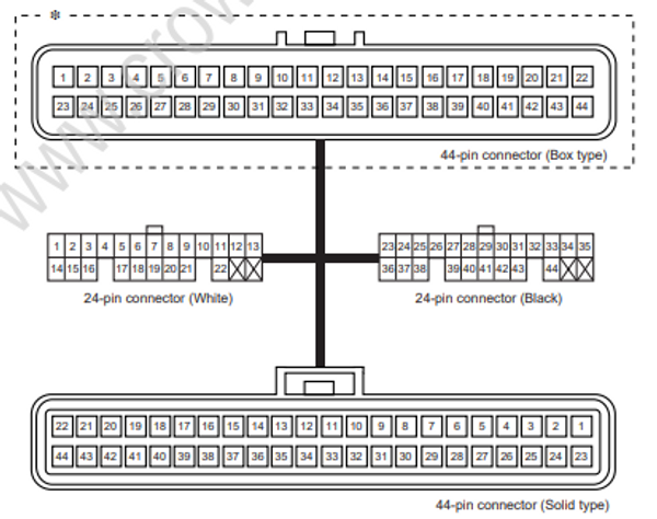
ECM INTERNAL STRUCTURE

SENSOR AND RELATED COMPONENTS
For more accurate control and simplification of structure, CKP sensor and related components have been modified.
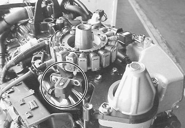
CKP SENSOR
Number of pickup coil of CKP sensor assy has been modified from 3 pieces to 1 piece.
FLYWHEEL MAGNETO
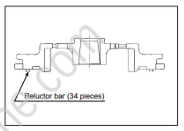
Number of reluctor bar (trigger vane) on the flywheel magneto has
been modified from 1 piece to 34 pieces.
CMP SENSOR / INTAKE CAMSHAFT
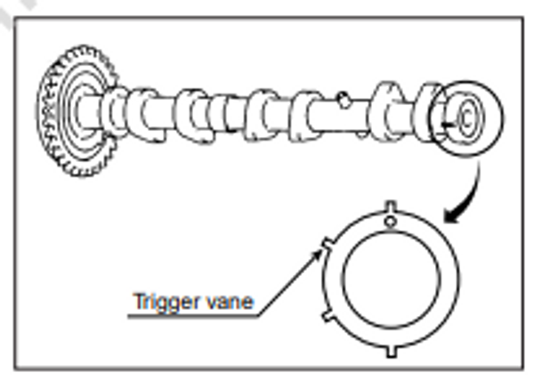
The CMP sensor on the “K1” (‘01) model is the same as the one
on the previous year models, number of trigger vane on the sensing rotor installed to the intake camshaft, however, has been modified from 1 piece to 4 pieces.
