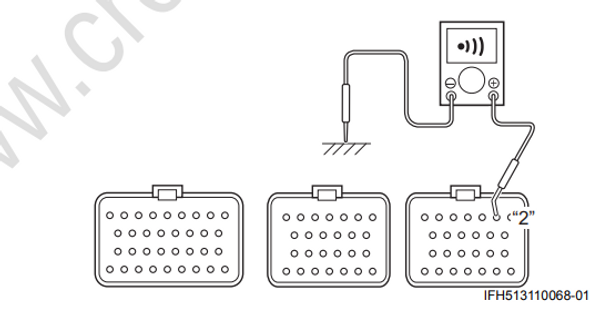
Self-Diagnostic Code “4 — 1” Model Distinction Switch
Wiring Diagram
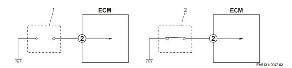
| 1. Regular select connector | 2. Counter select connector |
|---|
Troubleshooting
Step 1
Disconnect the ECM connectors from ECM with the main switch “OFF".
Check the ECM connector for loose or poor contacts.
If OK, then check the continuity between No. 2 terminal of ECM connector (harness side) and engine body ground.
No. 2 terminal continuity
Regular rotation condition: No continuity
Counter rotation condition: Continuity
Is the result OK?
Yes Counter/ Regular select connector and its circuit are in good condition.
No
- Faulty counter / regular select connector.
- “O/Y" wire shorted to “B” wire, “O/Y" wire open, poor “O/Y" wire connection, or poor counter/ regular select connector connection.
- If the wiring and connection is OK, intermittent trouble or a faulty ECM.