

General Description
Ignition System Description
The ignition system used by DF200AP is a fully transistorized, electronic microcomputer timing advanced type.
This system is totally battery powered, with the ECM controlling all ignition timing functions.
The ignition system is composed of the ignition coil, spark plug and components for system control (ECM, sensor, switch etc.).
When the main switch is “ON”, battery voltage (12 V) is applied to the circuit as shown in the illustration.
The ECM determines the optimum ignition timing and duration of current flowing through the ignition coil primary winding based on the signals received from various sensors.
The ECM interrupts the base current of the power transistor inside the ignition coil thereby controlling current flow (ignition) to the primary winding of ignition coil.
In this way, a mutual induction high voltage occurs in the ignition coil secondary side and spark is generated.
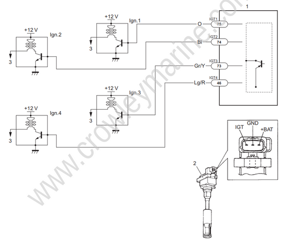
| 1. ECM |
| 2. Ignition coil |
| 3. Spark plug |
Ignition Control Description
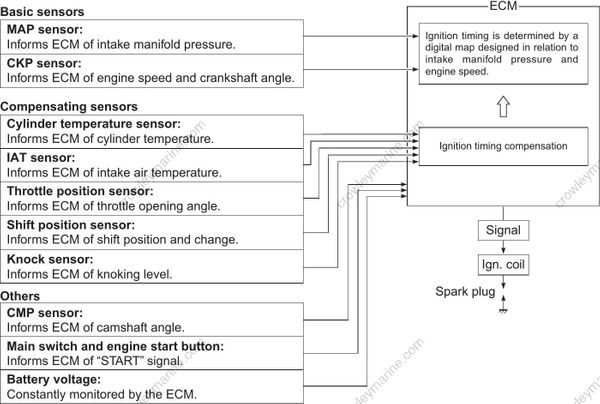
Sensors at specific points on the engine monitor current engine conditions and send signals to the ECM.
Ignition Specification
| Ignition system | Full-transistorized ignition |
| Advance | Electronic microcomputer control |
| Ignition timing | 0° ± 6° BTDC – 26° BTDC |
| Firing order | 1 — 3 — 4 — 2 |
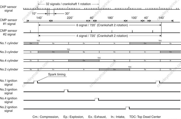
Ignition Timing Chart
The following chart is an example for ignition at 10° BTDC.
Control Mode
- When cranking
The ignition timing is fixed at 5° BTDC until the engine starts.
- When idling/trolling
The ignition timing is controlled within the range of 0° ± 6° BTDC to provide stable engine operation at the specified idling/trolling speed.
- When running (normal operation)
The ignition timing ranges between 0° BTDC – 26° BTDC, depending on current engine operating conditions.
- Knock control compensation
This compensation is added when knocking is detected so as to recover from knocking state immediately.
Component Location
Ignition System Components Location
Refer to “Wiring Harness Routing Diagram” in Section 4A (Page 4A-4).
Diagnostic Information and Procedures
Ignition System Symptom Diagnosis
| Condition | Possible cause | Correction / Reference Item |
|---|---|---|
| Engine cranks, but will not start or weak spark. (No spark) | Blown fuse for ignition system. | Replace. |
| Engine cranks, but will not start or weak spark. (No spark) | Loose connection or disconnection of lead wire. | Connect securely |
| Engine cranks, but will not start or weak spark. (No spark) | Faulty spark plug(s). | Replace. |
| Engine cranks, but will not start or weak spark. (No spark) | Faulty ignition coil. | Replace. |
| Engine cranks, but will not start or weak spark. (No spark) | Faulty CKP sensor. | Replace. |
| Engine cranks, but will not start or weak spark. (No spark) | Faulty CMP sensor or sensor trigger vane of camshaft | Replace. |
| Engine cranks, but will not start or weak spark. (No spark) | Faulty ECM | Replace. |
| Spark plug is wet or quickly becomes fouled with carbon. | Incorrect gasoline | Change. |
| Spark plug is wet or quickly becomes fouled with carbon. | Incorrect spark plug | Replace. |
| Spark plug quickly become fouled with oil or carbon. | Worn piston ring. | Replace. |
| Spark plug quickly become fouled with oil or carbon. | Worn piston. | Replace. |
| Spark plug quickly become fouled with oil or carbon. | Worn cylinder. | Replace. |
| Spark plug quickly become fouled with oil or carbon. | Excessive valve stem to valve guide clearance. | Replace. |
| Spark plug quickly become fouled with oil or carbon. | Worn valve stem seal. | Replace. |
| Spark plug electrodes overheat or burn | Incorrect spark plug. | Change. |
| Spark plug electrodes overheat or burn | Overheated engine. | Tune-up. |
| Spark plug electrodes overheat or burn | Loose spark plug. | Tighten. |
Ignition System Troubleshooting
Before starting the troubleshooting, make sure that:
There is not self-diagnostic code indication.
Emergency stop switch plate is set in place.
Perform the following ignition system tests when the engine is hard to start in order to determine if the cause is in the ignition or another system.
Step 1
Check the ignition system connector for poor connections. Is there connection in the ignition system connectors?
| Yes | Go to step 2 |
| No | Poor connection of connectors |
Step 2
Check spark condition.
| Yes | Go to step 3. |
| No | No or weak sparks. |
Step 3
Check if the spark plugs are in good condition.
| Yes | Go to step 4. |
| No | Replace spark plug with a new one. |
Step 4
Check ignition coil assembly power supply and ground circuits for open and short. Are circuits in good condition?
| Yes | Go to step 5. |
| No | Repair or replace. |
Step 5
Check ignition coil operating signal. Is result OK?
| Yes | Go to step 6 |
| No | Check ignition coil operating signal wire for open, short and poor connection. |
Step 6
Measure the battery voltage between input lead wire at ECM with the main switch in “ON” position. Is result OK?
| Yes | Go to step 7. |
| No | • Faulty main switch. • Faulty ECM main relay. • Broken wire harness or poor connection of related circuit connector. |
Step 7
Check CKP sensor. Refer to “CKP Sensor Inspection” in Section 1C (Page 1C-13). Is result OK?
| Yes | Go to step 8 |
| No | • Check air gap between CKP sensor and flywheel reluctor bars. • Adjust CKP sensor air gap. • Replace CKP sensor or flywheel. |
Step 8
Check CMP sensor. Refer to “CMP Sensor Inspection” in Section 1C (Page 1C-15). Is result OK?
| Yes | Go to step 9 |
| No | • Check CMP sensor. • Check CMP sensor trigger vane. • Replace CMP sensor or Ex. camshaft |
Step 9
Substitute a known-good ignition coil assembly then repeat step 2. Is check result of step 2 satisfactory?
| Yes | Go to step 10. |
| No | Substitute a known good ECM, then repeat step 2. |
Step 10
Check the ignition timing by using timing light (Approx. 3° BTDC at 1 000 r/min). Is result OK?
| Yes | System is in good condition. |
| No | Check input signals related to this system |
Service Instructions
Spark Plug Removal and Installation
Refer to “Spark Plug Removal and Installation” in Section 0B (Page 0B-7).
Spark Plug Inspection
Refer to “Spark Plug Inspection and Cleaning” in Section 0B (Page 0B-8).
Ignition Coil Removal and Installation
Removal
Disconnect the battery cables from the battery.
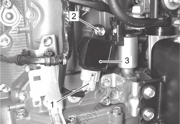
Disconnect the ignition coil connector (1).
Remove the bolt (2) securing the ignition coil, then pull out the ignition coil (3).
Installation
Install the ignition coil, then secure the ignition coil with its mounting bolt.
Connect the ignition coil connector.
Connect the battery cables to battery.
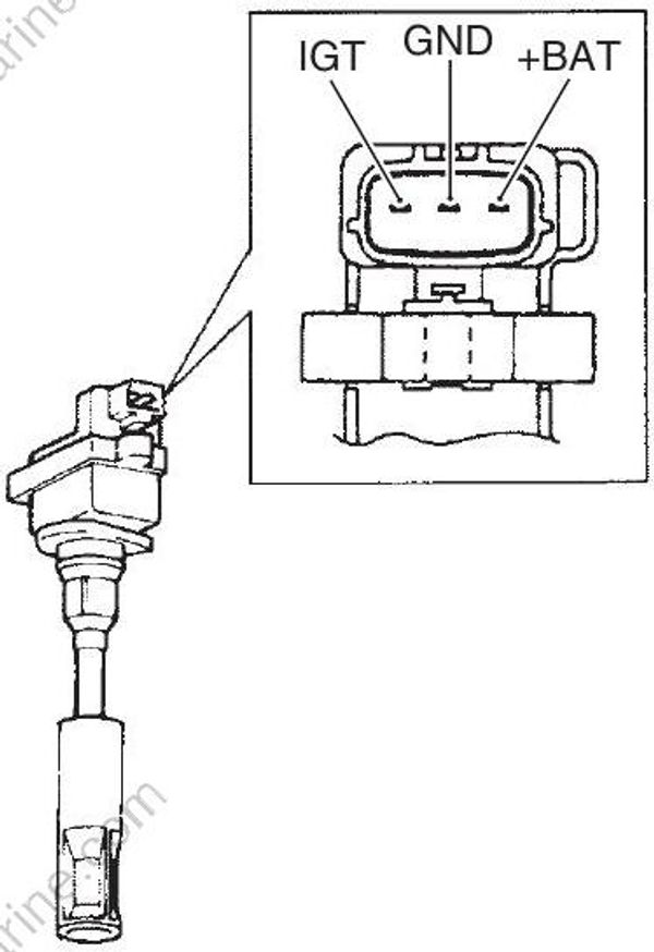
Ignition Coil Inspection
The ignition coil power transistor and high tension lead are an integral part of the coils internal circuit. Using resistance measurements to check for a defect on either the primary or secondary coil is not possible.
Special tool
(A): 09900–25008 (Multi circuit tester set)
Tester knob indication
DCV
Turn the main switch OFF.
Disconnect the ignition coil connector.
Check for continuity between the GND (–) terminal on the wiring harness side connector and the engine body ground.
Turn the main switch key to the ON position. Check for battery voltage by measuring between the BAT (+) terminal and GND terminal on the wiring harness side connector.
Connect the wiring harness connector to the ignition coil and measure the ignition operating signal.
Refer to “Ignition Coil Operating Signal Inspection” (Page 1H-7).
If any failure exists, check for open circuit, short circuited battery, short circuited lead and connector’s contact condition for each circuit.
If there is no spark even with the wiring harness and spark plug in sound condition, perform the inspection again using an ignition coil that is known to be in good condition (new or used from another cylinder that is operating properly).
If there is still no spark even with the wiring harness, spark plug and ignition coil in sound condition, replace the ECM and perform the inspection again.
Ignition Coil Operating Signal Inspection
Special tool
(A): 09930–89340 (26-pin & 34-pin test cord)
(B): 09930–89850 (26-pin (B) test cord)
Stevens peak reading voltmeter CD-77
Tester knob indication
SEN 50
Disconnect all injector connectors from the fuel injectors.
Connect test cords between ECM and wire harness as shown in figure, then turn main switch ON.
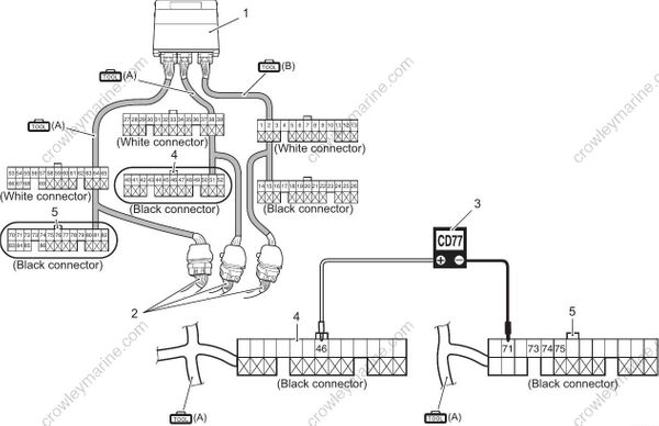
| 1. ECM |
| 2. Wire harness |
| 3. Stevens peak reading voltmeter CD-77 |
| 4. Black connector (26-pin) |
| 5. Black connector (34-pin) |
- Connect the tester probe (“+”, Red) to each terminal.
| Ignition coil | Terminal | Wire color (engine harness) |
|---|---|---|
| No.1 | 75 | O |
| No.2 | 74 | Bl |
| No.3 | 73 | Gr/Y |
| No.4 | 46 | Lg/R |
Connect the tester probe (“–” Black) to No.71 terminal (or to body ground).
Crank engine and measure voltage.
If out of specification, inspect the related parts.
Refer to “Ignition System Symptom Diagnosis” (Page 1H-4) and “Ignition System Troubleshooting” (Page 1H-5).
Ignition coil operating signal
Standard: Approx. 5 V
CKP Sensor Inspection
Refer to “CKP Sensor Inspection” in Section 1C (Page 1C-13).
CMP Sensor Inspection
Refer to “CMP Sensor Inspection” in Section 1C (Page 1C-15).
Main Switch Inspection
Refer to “Main Switch Inspection” in Section 1I.
ECM Main Relay Inspection
Refer to “ECM Main Relay Inspection” in Section 1A (Page 1A-85).
