Precautions
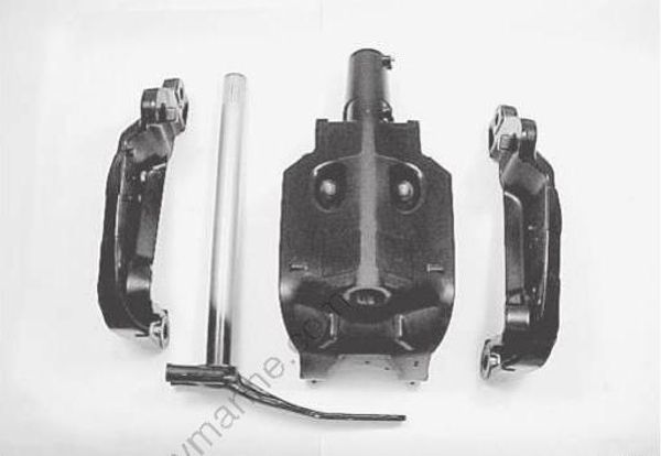
Precaution for Housing and Bracket
Do not break or cut bonding wires, as they perform an important function in the prevention of galvanic corrosion or build up of static charges. Replace any damaged wire.
• When disassembling housing and bracket, inspect mountings and bolts for damage and wear. Replace if necessary.
• Check the condition of the zinc anodes on lower section of mid unit. Replace if necessary.
Service Instructions
Lower Side Cover Components
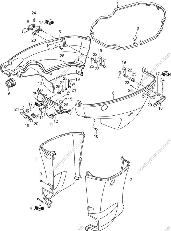
| 1. Oil pan cover STBD |
| 2. Oil pan cover PORT |
| 3. Screw |
| 4. Bolt |
| 5. Lower side cover STBD |
| 6. Lower side cover PORT |
| 7. Side cover seal |
| 8. Pin |
| 9. Grommet |
| 10. Screw |
| 11. Plug |
| 12. Gasket |
| 13. Front panel |
| 14. Bolt |
| 15. Washer |
| 16. Cushion |
| 16. Cushion |
| 18. Engine cover hook lever |
| 19. Engine cover hook |
| 20. Latch |
| 21. Bolt |
| 22. Washer |
| 23. Washer |
| 24. Pin |
| 25. Bushing |
| 26. Screw |
| Apply SUZUKI Water Resistant Grease. |
Lower Side Cover Removal and Installation
Removal
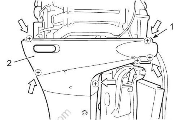
- Remove six screws (1) and STBD side cover (2).
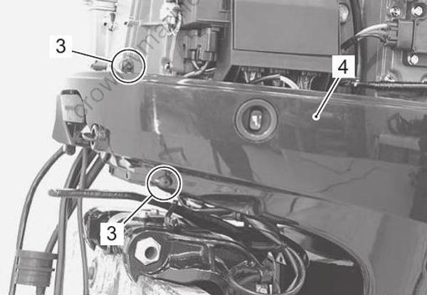
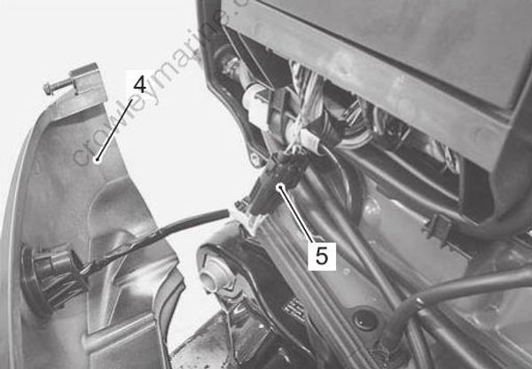
- Remove two screws (3) and PORT side cover (4).
- Disconnect PTT switch lead wire connector (5).
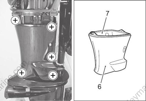
- Remove five screws and STBD/PORT oil pan covers (6) and (7).
Installation
Installation is reverse order of removal.
Engine Holder / Oil Pan / Driveshaft Housing / Mounts Components
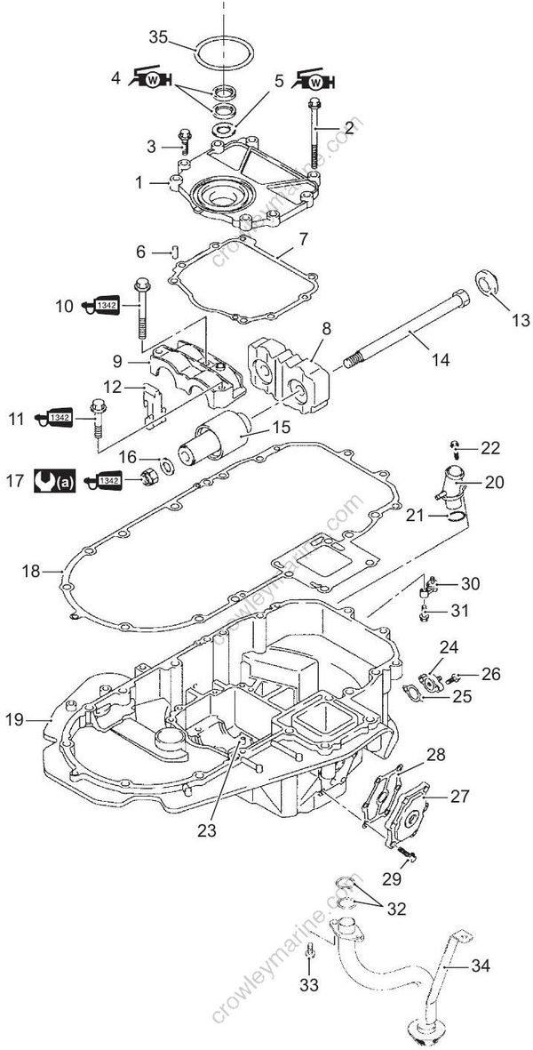
| 1. Mount oil seal cover |
| 2. Bolt |
| 3. Bolt |
| 4. Oil seal |
| 5. Scraper |
| 6. Pin |
| 7. Gasket |
| 8. Upper thrust mount |
| 9. Upper mount cover |
| 10. Bolt |
| 11. Bolt |
| 12. Upper side mount |
| 13. Spacer |
| 14. Upper mount bolt |
| 15. Upper mount |
| 16. Washer |
| 17. Nut |
| 18. Gasket |
| 19. Engine holder |
| 20. Water return union |
| 21. O-ring |
| 22. Bolt |
| 23. Pin |
| 24. Engine holder cover |
| 25. Gasket |
| 26. Bolt |
| 27. Water jacket cover |
| 28. Gasket |
| 29. Bolt |
| 30. Water indicator |
| 31. Bolt |
| 32. O-ring |
| 33. Bolt |
| 34. Oil strainer |
| 35. O-ring |
| : 100 N-m (10 kgf-m, 72.5 lbf-ft) |
| : Apply SUZUKI Water Resistant Grease |
| : Apply SUZUKI Thread Lock 1342. |
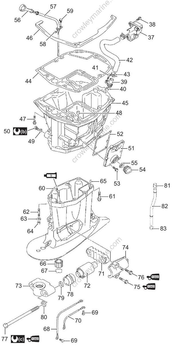
| 37. Exhaust release pipe |
| 38. Bolt |
| 39. Exhaust pipe |
| 40. O-ring |
| 41. Bolt |
| 42. Hose |
| 43. Clip |
| 43. Clip |
| 45. Oil pan |
| 46. Seal |
| 47. Bolt |
| 48. Pin |
| 49. Gasket |
| 50. Oil drain plug |
| 51. Water jacket cover |
| 52. Gasket |
| 53. Bolt |
| 54. Plug |
| 55. Gasket |
| 56. Oil level gauge |
| 57. Oil level gauge guide |
| 58. O-ring |
| 59. Bolt |
| 60. Driveshaft housing |
| 61. Bolt |
| 62. Stud bolt |
| 63. Washer |
| 64. Nut |
| 65. Pin |
| 66. Bushing (Type: X) |
| 67. Ring |
| 68. Bonding wire |
| 69. Screw |
| 69. Screw |
| 71. Lower thrust mount |
| 72. Lower mount |
| 73. Lower mount bracket |
| 74. Lower mount cover |
| 75. Bolt |
| 76. Bolt |
| 77. Lower mount bolt |
| 78. Lower side mount |
| 79. Washer |
| 80. Washer |
| 81. Bushing |
| 82. Water tube |
| 83. Bushing |
| : 13 Nm (1.3 kgf-m, 9.5 lbf-ft) |
| : 100 Nm (10 kgf-m, 72.5 lbf-ft) |
| : Apply SUZUKI Thread Lock 1342 |
| : Apply SUZUKI Silicone Seal. |
Engine Holder / Oil Pan / Driveshaft Housing / Mounts Disassembly
- Remove power unit.
Refer to “Power Unit Removal and Installation” in Section 1D (Page 1D-19).
- Remove lower unit.
Refer to “Lower Unit Removal and Installation” in Section 3C (Page 3C-6).
- Remove E-ring (1) from clutch lever shaft.
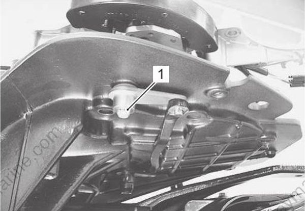
- Remove two bolts and clutch holder (2).
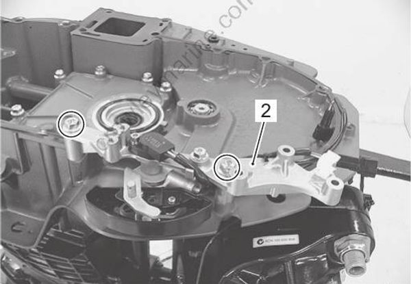
- Remove pin (3), hose union “A” and side cover seal (4).
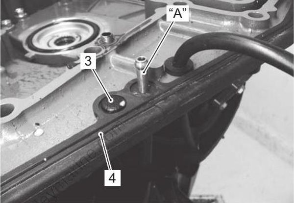
IFH511210017-01
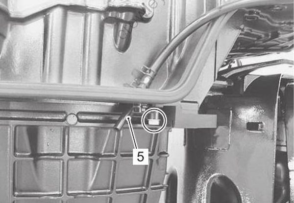
- Remove bolt and pilot water tube (5).
- Disconnect water hose (oil pan to 3 way joint) (6) from oil pan water jacket cover (7).
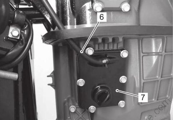
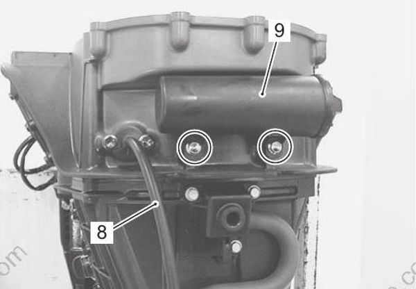
- Remove water hose (engine holder cover to cylinder block) (8).
Remove two bolts and vacuum tank (9).
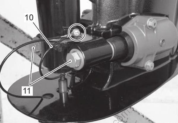
- Operate the PTT motor to extend the PTT rod upward.
Special tool : 09945–79310 (PTT cable extension)
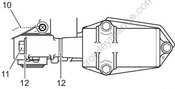
- Remove the screw and bonding wire (10).
Unscrew and remove STBD/PORT lower mount bolts (11).
Account for washers (12).
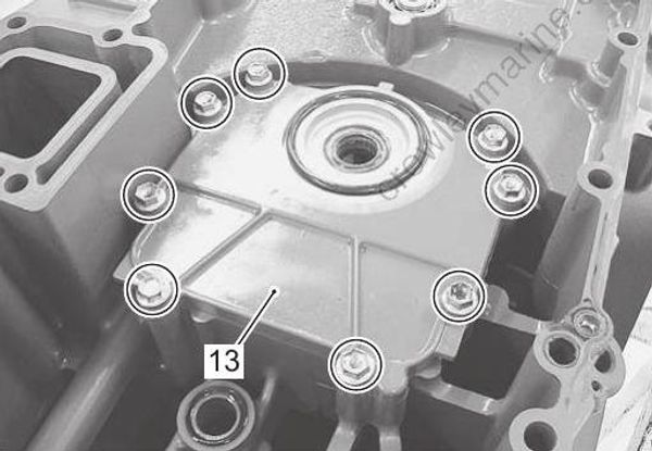
- Remove eight bolts and mount oil seal cover (13).
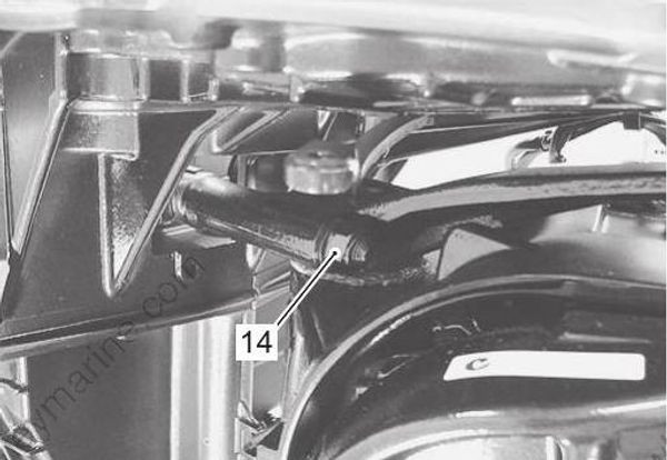
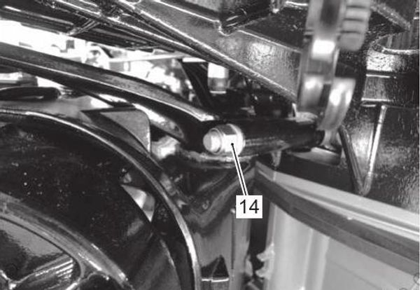
- Remove STBD/PORT upper mount nuts (14) and washers.
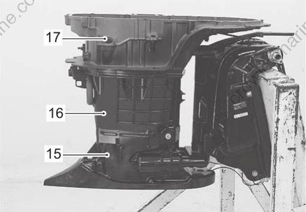
- Remove driveshaft housing (15) with oil pan (16) and engine holder (17).
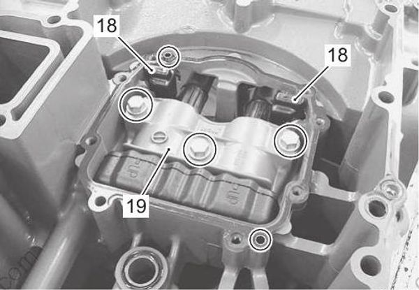
- Remove the upper side mounts (18).
Remove three bolts and upper mount cover (19).
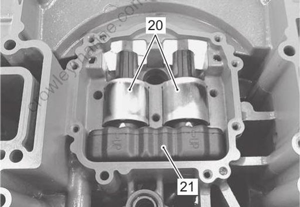
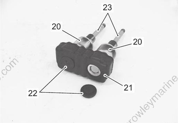
- Remove upper mounts (20), thrust mount (21), spacer (22) and mount bolts (23).
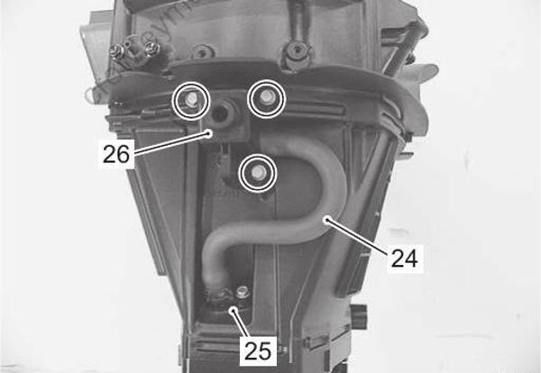
- Loosen the clamp securing exhaust hose (24), then remove the exhaust hose from exhaust pipe (25).
Remove the three bolts securing exhaust relief pipe (26), then remove exhaust relief pipe.
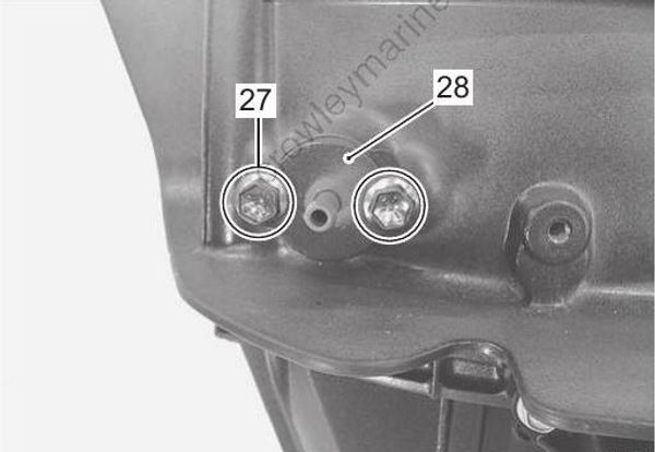
- Remove two bolts (27) and engine holder cover (28).
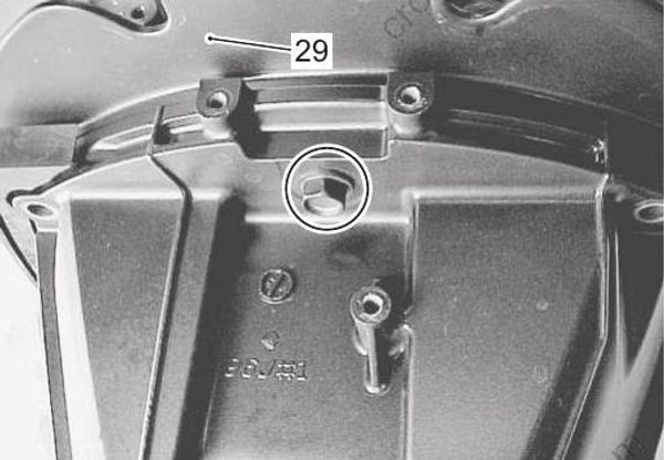
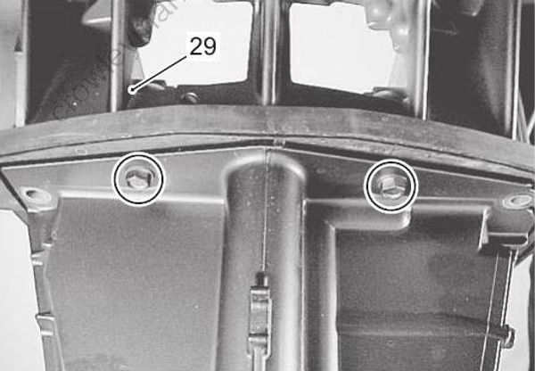
- Remove three bolts and engine holder (29).
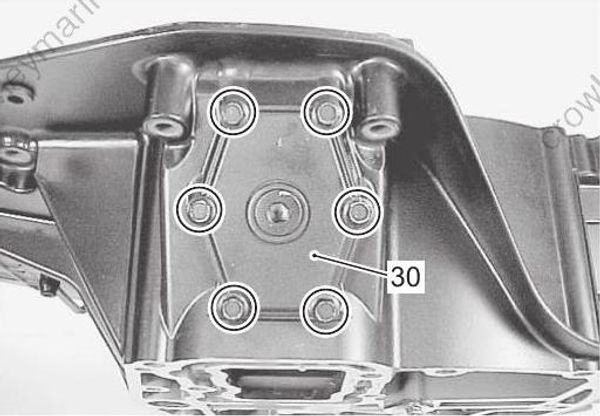
- Remove six bolts and water jacket cover (30).
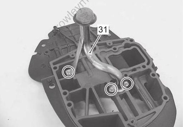
- Remove three bolts and oil strainer (31).
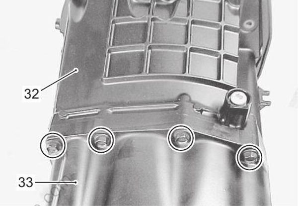
- Remove eight bolts, then remove oil pan (32) from driveshaft housing (33).
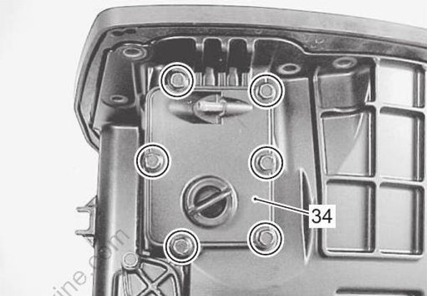
- Remove six bolts and oil pan water jacket cover (34).
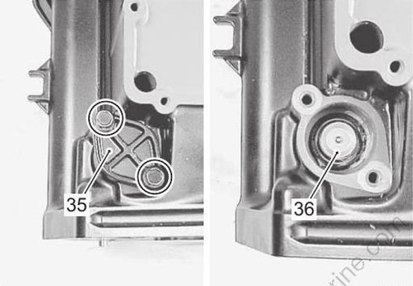
- Remove bolts, water pressure valve cover (35) and water pressure valve (36).
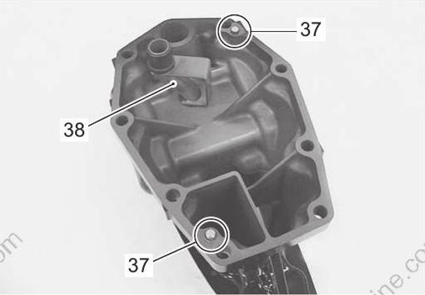
- Remove dowel pins (37).
Remove water tube (38).
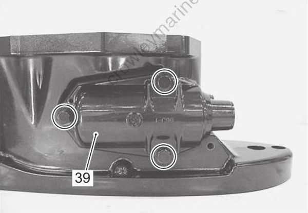
- Remove bolts and lower mount covers (39).
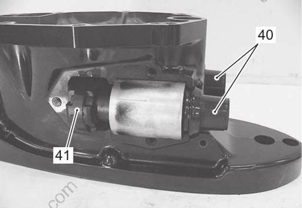
- Remove lower mounts (40) and lower thrust mount (41).
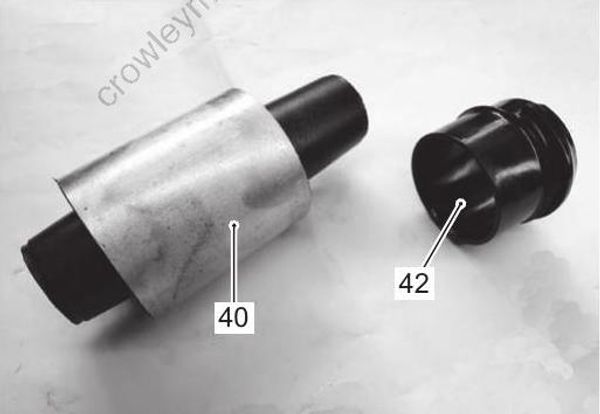
- Remove the lower side mount (42) from lower mount (40).
Engine Holder / Oil Pan / Driveshaft Housing / Mounts Assembly
Assembly is reverse order of disassembly with special attention to the following steps.
Lower Mount / Mount Cover
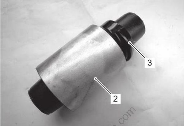
- Assemble the lower mount (2) and lower side mount (3).
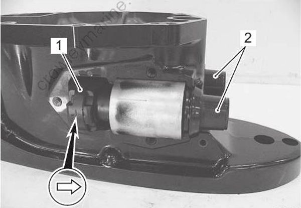
Install lower thrust mount (1) with the arrow mark facing forward.
Install lower mounts (2).
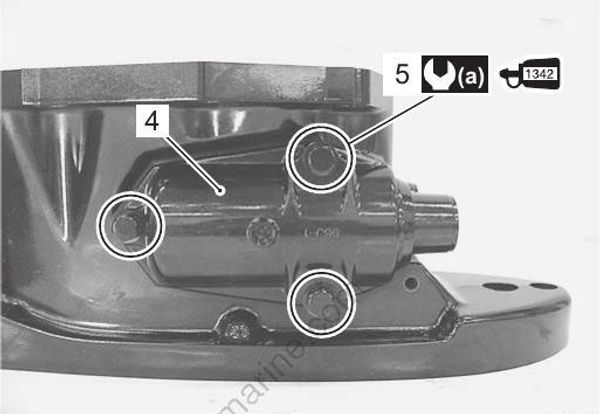
Install lower mount covers (4).
Tighten mount cover bolts (5), pre-coated with thread lock, to specified torque.
Thread lock cement 99000–32050 (SUZUKI Thread Lock 1342 (50 g))
Tightening torque
Lower mount cover bolt (a): 50 N·m (5.0 kgf-m, 36.0 lbf-ft)
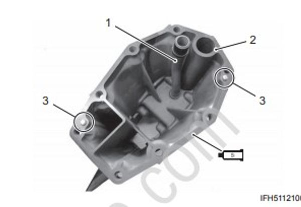
Oil Pan to Driveshaft Housing
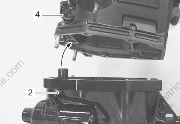
Install water tube (1) to driveshaft housing (2).
Install two dowel pins (3).
Apply silicone seal to mating surfaces of driveshaft housing and oil pan.
Sealant 93691–80030 (SUZUKI Silicone Seal (100 g))
- Install water pressure valve to oil pan.
Refer to “Water Pressure Valve Removal and Installation” in Section 1F (Page 1F-5).
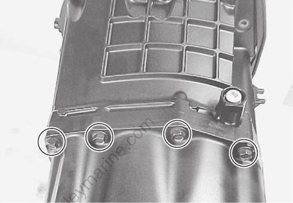
- Install the oil pan (4) to driveshaft housing (2) by
aligning the water tube with the oil pan water passage. Tighten the eight bolts securely.
Engine Holder to Oil Pan
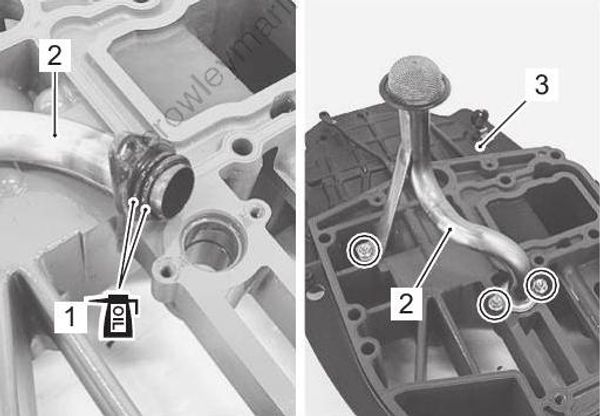
Apply engine oil to O-rings (1), then install O-rings to oil strainer (2).
Install oil strainer to engine holder (3), then tighten bolts securely.
- Install two dowel pins (4) and gasket (5) to oil pan.
Previously used gasket may leak oil and/or cooling water, resulting in engine damage.
Do not reuse gasket. Always assemble with a new gasket.
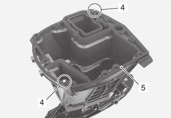
- Install engine holder (3) to oil pan, then securely tighten it with engine holder bolts (6).
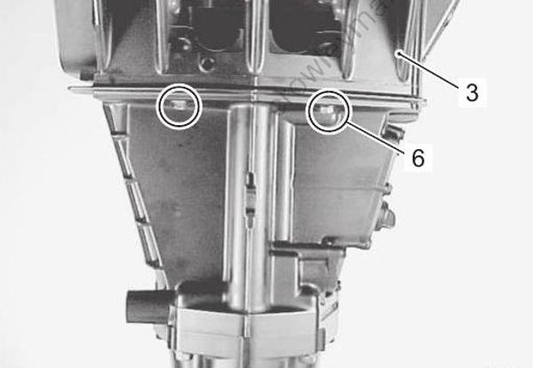
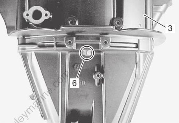
Upper Mount and Mount Cover
- Assemble these items in the following sequence:
Place upper thrust mount (1) and upper mounts (2) on upper mount bolts (3).
- Install spacers (4) to thrust mount.
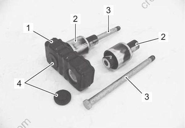
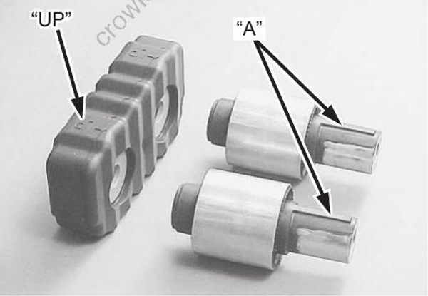
- Place upper mount assembly into position.
• Position the projection “A” on upper mount tube to upper (flywheel) side.
• Install upper thrust mount with the lettered mark “UP” facing upward.
- Install the upper mount cover (5) and tighten the mount cover bolts, pre-coated with thread lock, to specified torque.
Thread lock cement 99000–32050 (SUZUKI Thread Lock 1342 (50 g))
Tightening torque
Upper mount cover bolt (a): 50 N·m (5.0 kgf-m, 36.0 lbf-ft)
- Install the upper side mounts (6).
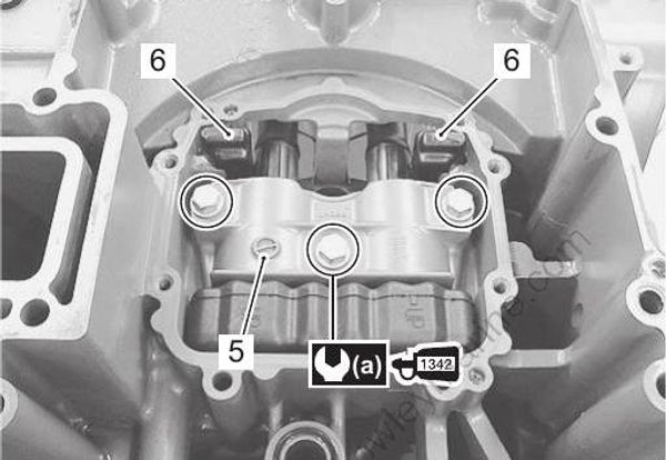
Driveshaft Housing / Oil Pan • Install driveshaft housing with
Install driveshaft housing with oil pan and engine holder to steering bracket.
Install washer (1) and upper mount nut (2), then tighten two nuts, pre-coated with thread lock, to specified torque.
Thread lock cement 99000–32050 (SUZUKI Thread Lock 1342 (50 g))
Tightening torque
Upper mount nut (a): 100 N·m (10.0 kgf-m, 72.5 lbf-ft)
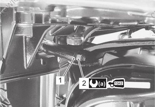
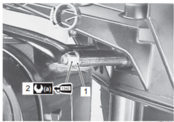
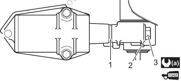
Lower Mount Bolt
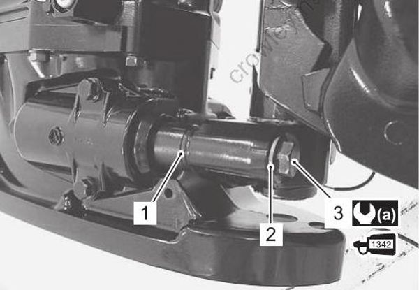
Place washer (1) between lower mount and lower mount bracket.
Install washer (2) and lower mount bolt (3), then tighten bolt, pre-coated with thread lock, to specified torque.
Thread lock cement 99000–32050 (SUZUKI Thread Lock 1342 (50 g))
Tightening torque
Lower mount bolt (a): 100 N·m (10.0 kgf-m, 72.5 lbf-ft)
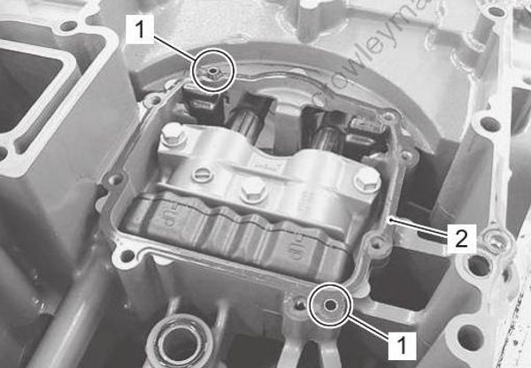
Mount·oil Seal Cover
- Install dowel pins (1) and gasket (2).
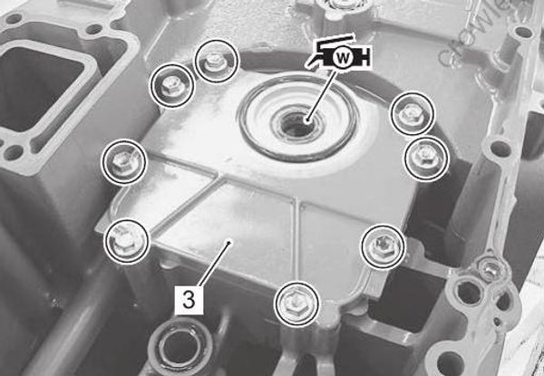
Install mount-oil seal cover (3), then tighten eight cover bolts securely.
Apply Water Resistant Grease to oil seal.
Grease 99000–25350 (SUZUKI Water Resistant Grease EP2 (250 g))
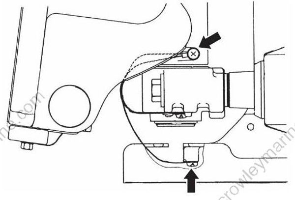
Bonding Wire
- Reattach bonding wire, then tighten screw securely.
Clutch Holder
- Install clutch holder (1) to engine holder, then tighten bolts securely.
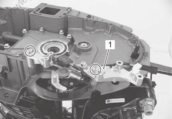
- Install clutch lever shaft arm (2) and E-ring (3).
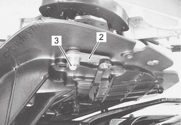
- Install lower unit.
Refer to “Lower Unit Removal and Installation” in Section 3C (Page 3C-6).
- Install power unit.
Refer to “Power Unit Removal and Installation” in Section 1D (Page 1D-19).
Engine Holder / Oil Pan / Driveshaft Housing / Mounts Related Component Inspection
Refer to “Engine Holder / Oil Pan / Driveshaft Housing / Mounts Disassembly” (Page 2A-6) and “Engine Holder / Oil Pan / Driveshaft Housing / Mounts Assembly” (Page 2A-10).
If any component is found to be excessively worn, cracked, defective or damaged in any way, it must be replaced.
Engine Holder
Inspect the engine holder. Replace if cracked, damaged, or other abnormal conditions are noted.
Check water passage. If clogged or obstructed, clean water passage.
Visually check the clutch shaft bearing. Replace if pitted, noisy, rough or other abnormal conditions are found.
Refer to “Clutch Shaft Bearing and Oil Seal Replacement” (Page 2A-15).
- Check the clutch shaft oil seal. Replace the oil seal if nicked, cut, worn or other abnormal conditions are found.
Refer to “Clutch Shaft Bearing and Oil Seal Replacement” (Page 2A-15).
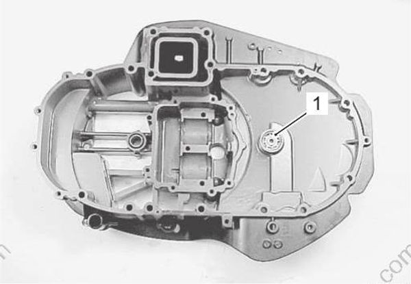
- Bearing
Mount Oil Seal Cover
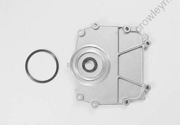
Inspect the mount oil seal cover. Replace the mount oil seal cover if cracked, damaged or other abnormal condition are found.
Check condition of O-ring. Replace O-ring if nicked, cut, worn or other abnormal condition are found.
Check condition of oil seal. Replace oil seal if nicked, cut, worn or other abnormal condition are found.
Refer to “Mount Oil Seal Cover Oil Seal Replacement” (Page 2A-17).
Oil Strainer
- Inspect the oil strainer. Replace the strainer if cracked, damaged or other abnormal conditions are found.
If clogged or obstructed, clean the oil strainer.
- Check condition of O-rings. Replace O-ring if nicked, cut, worn or other abnormal condition are found.
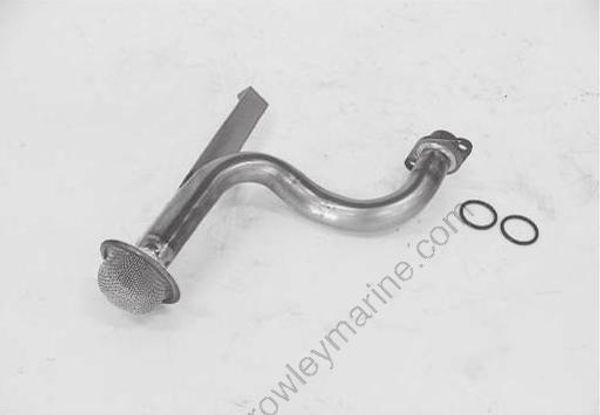
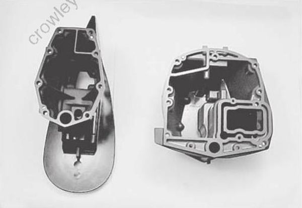
Oil Pan / Driveshaft Housing
- Check oil pan, driveshaft housing.
If cracks, defects or other damage is found, replace it.
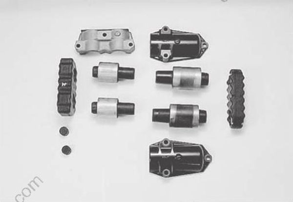
Mounts
- Check upper, lower and thrust mounts.
If excessive wear, corrosion or other damage is found, replace mount.
- Inspect mount cover. Replace mount cover if cracked, damaged or other abnormal conditions are found.
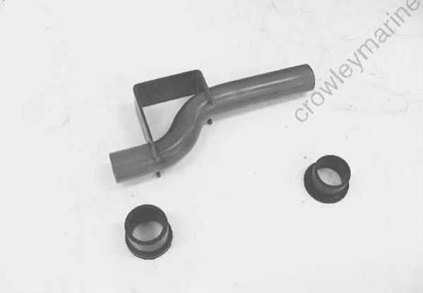
Water Tube / Water Tube Grommet
- Check water tube.
If a clog or obstruction is found, clean water tube.
If cracks, corrosion or other damage is found, replace water tube.
- Check water tube grommet.
If excessive wear or other damage is found, replace grommet.
Clutch Shaft Bearing and Oil Seal Replacement
- Remove the engine holder.
Refer to “Engine Holder / Oil Pan / Driveshaft Housing / Mounts Disassembly” (Page 2A-6).
- Loosen and remove clutch shaft plug (1).
Remove clutch shaft (2).
Remove circlip (3).
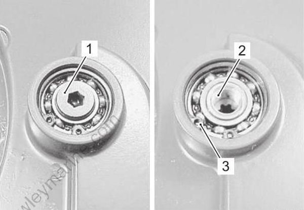
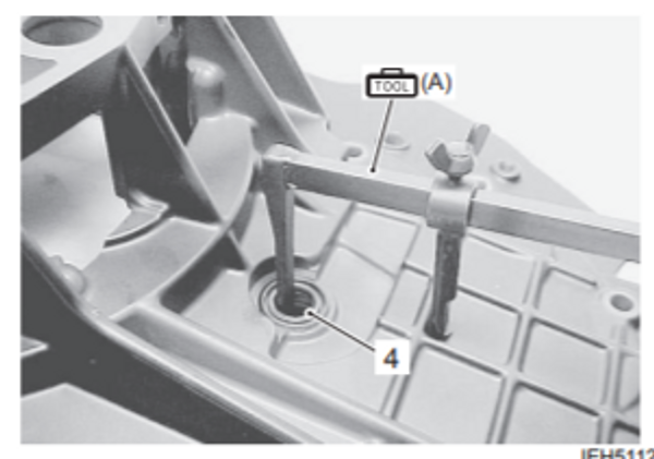
- Extract oil seal (4) with oil seal remover.
Removing the oil seal can cause damage to the seal lips, causing oil to leak.
Do not reuse oil seal once removed. Always use a new oil seal.
Special tool
(A): 09913–50121 (Oil seal remover)
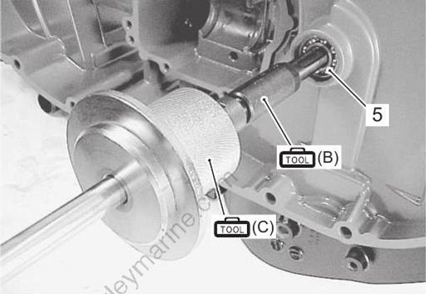
- Remove bearing (5) with special tool and sliding hammer.
Removing the bearing can cause damage to the ball retainer.
If the removed bearing is re-used, problem will occur in shift system.
Do not reuse the bearing once removed. Always use a new bearing.
Special tool
(B): 09923–73210 (Bearing remover)
(C): 09930–30104 (Sliding hammer)
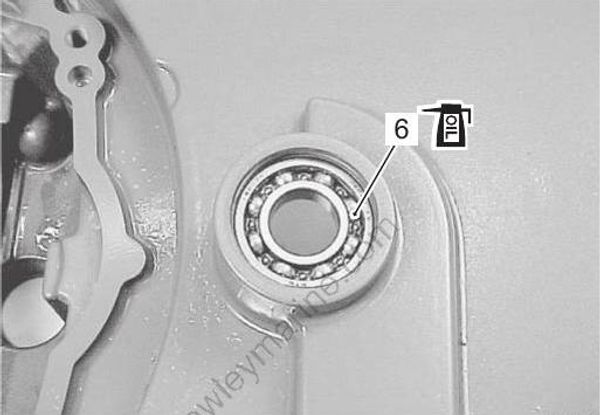
- Apply engine oil to outer circumference of new bearing (6).
Install bearing (6) into engine holder.
- Apply water resistant grease to outer circumference of oil seal (7).
Drive oil seal into engine holder.
Apply water resistant grease to the seal lip.
Install oil seal as shown in the figure.
Grease 99000–25350 (SUZUKI Water Resistant Grease EP2 (250 g))
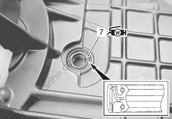
- Install circlip (3).
Install clutch shaft (2).
Tighten the clutch shaft plug (1), pre-coated with thread lock, to specified torque.
Tightening torque
Clutch shaft plug (a): 20 N·m (2.0 kgf-m, 14.5 lbf- ft)
Thread lock cement 99000–32050 (SUZUKI Thread Lock 1342 (50 g))
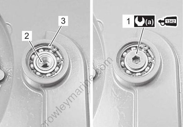
- Reassemble the engine holder.
Refer to “Engine Holder / Oil Pan / Driveshaft Housing / Mounts Assembly” (Page 2A-10).
Mount Oil Seal Cover Oil Seal Replacement
- Remove the mount oil seal cover.
Refer to “Engine Holder / Oil Pan / Driveshaft Housing / Mounts Disassembly” (Page 2A-6).
- Remove the oil seals (1).
Removing the oil seal can cause damage to the seal lips, causing oil to leak.
Do not reuse oil seal once removed. Always use a new oil seal.
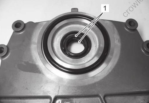
- Remove the scraper (2).
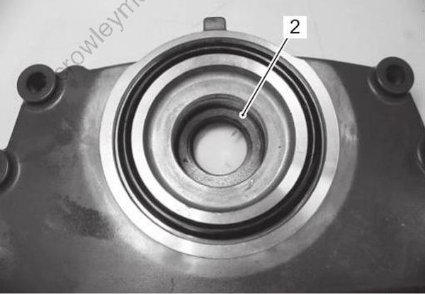
- Reinstall the scraper (2).
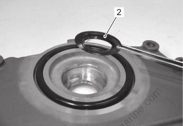
- Apply water resistant grease to outer circumference of oil seals.
Drive the two oil seals (one at a time) into the mount oil seal cover.
Apply water resistant grease to seal lips.
Install oil seal with lip (spring side) facing downward (oil pan side).
Grease 99000–25350 (SUZUKI Water Resistant Grease EP2 (250 g))
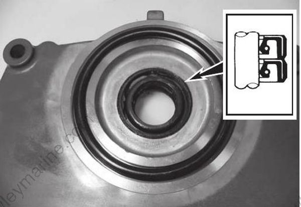
- Install the mount oil seal cover.
Refer to “Engine Holder / Oil Pan / Driveshaft Housing / Mounts Assembly” (Page 2A-10).
Clamp / Swivel / Steering Bracket Components
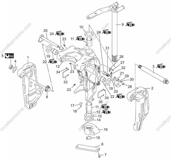
| 1. Clamp bracket STBD |
| 2. Clamp bracket PORT |
| 3. Clamp bracket shaft |
| 4. Washer |
| 5. Nut |
| 6. Anode |
| 7. Bolt |
| 8. Tilt limit switch cam |
| 9. Steering bracket |
| 10. Washer |
| 11. Bushing |
| 12. Swivel bracket |
| 13. Seal |
| 14. Shim |
| 15. Circlip |
| 16. Lower mount bracket |
| 17. Anode |
| 18. Bolt |
| 19. Washer |
| 20. Tilt lock lever |
| 21. Tilt lock lever PORT |
| 22. Bushing |
| 23. Grease nipple |
| 24. Bushing |
| 25. Tilt lock lever link |
| 26. Bracket |
| 27. Screw |
| 28. Nut |
| 29. Washer |
| 30. Pin |
| 31. Spring |
| 32. Spring |
| 33. Bonding wire |
| 34. Screw |
| 35. Bonding wire |
| : 43 Nm (4.3 kgf-m, 31.0 lbf-ft) |
| : Apply SUZUKI water resistance grease. |
Clamp / Swivel / Steering Brackets Disassembly
- Remove engine holder/oil pan and driveshaft housing.
Refer to “Engine Holder / Oil Pan / Driveshaft Housing / Mounts Disassembly” (Page 2A-6).
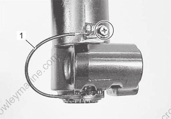
- Remove screw and bonding wire (1).
- Remove circlip (2).
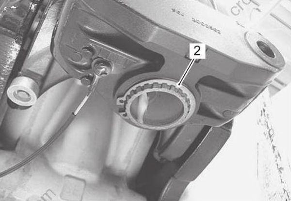
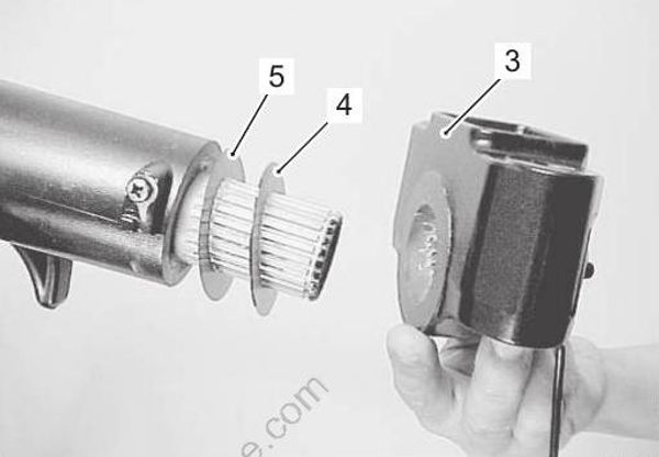
- Remove lower mount bracket (3), shims (4), and washer (5) from the steering shaft.
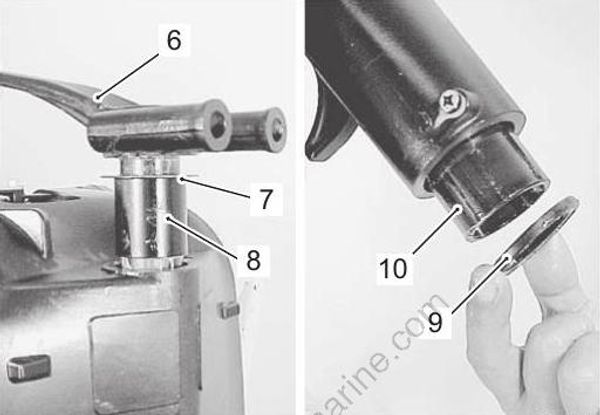
- Lift steering bracket (6) upward to remove from swivel bracket.
Remove washer (7) and upper bushing (8).
- Remove swivel bracket seal (9) and lower bushing (10).
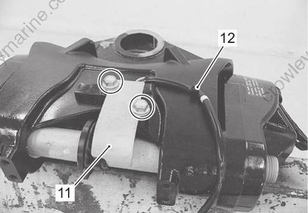
- Remove two bolts, switch cover (11) and tilt limit switch.
Cut the cable tie (12) securing switch lead wire.
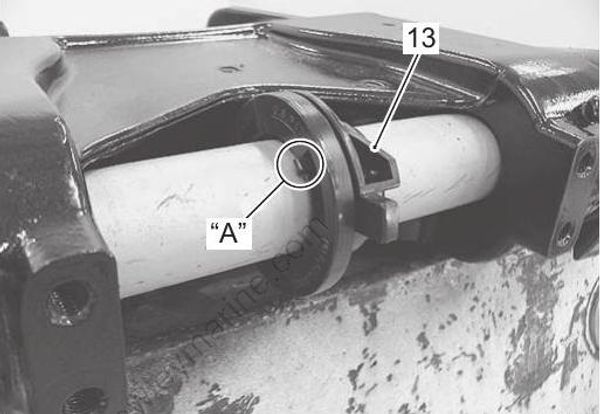
- Remove tilt limit switch cam (13).
Unfasten three stoppers “A” from the tilt limit switch cam to remove it from cam holder.
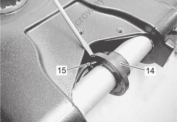
- Remove upper cam holder (14) and lower cam holder (15) from clamp bracket shaft.
Use thin flat screw-driver to release the two hooks to separate the cam holder upper and lower halves.
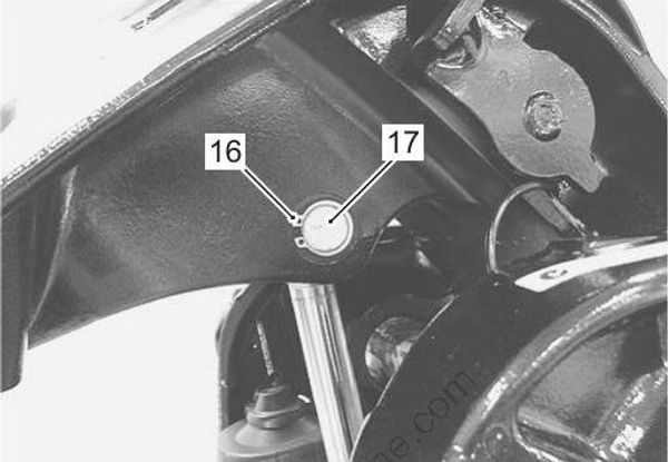
- Connect the special tool to PTT motor and raise the swivel bracket.
Special tool : 09945–79310 (PTT cable extension)
Remove circlip (16) and push out tilt cylinder upper rod (17).
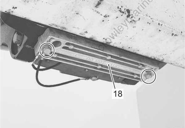
- Remove bolts and anode (18).
- Remove bolts (19) securing PTT unit to the STBD and PORT clamp brackets.
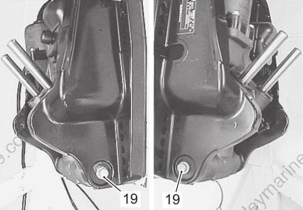
- Using flat screw-driver, drive locking edge of lock washer (20) to clamp bracket side.
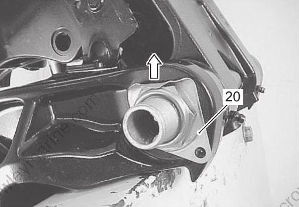
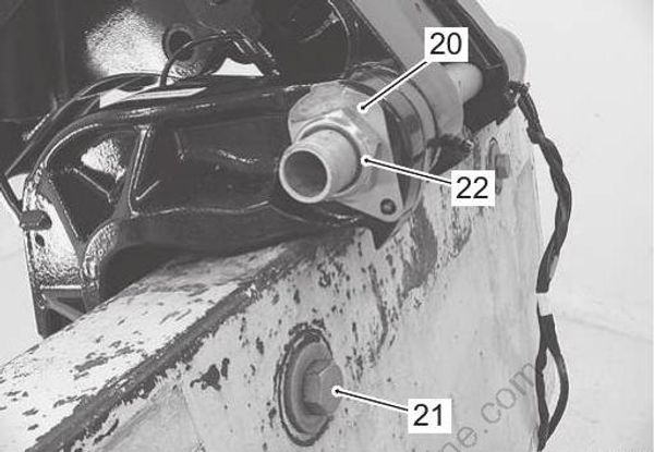
- Remove the two STBD motor mounting bolts (21). Remove the clamp bracket shaft nut (22) and lock washer (20).
- Remove the screw (23) securing bonding wire.
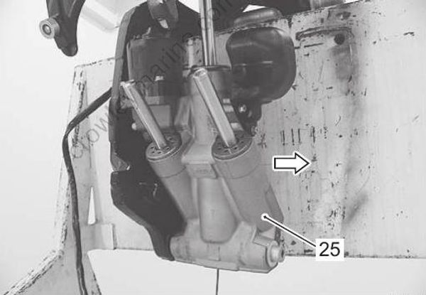
Slide STBD clamp bracket (24) off clamp bracket shaft, then remove PTT unit (25).
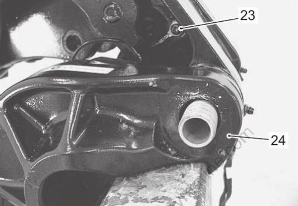
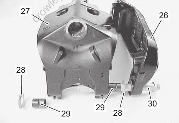
- Pull PORT clamp bracket (26) outward to remove clamp bracket and bracket shaft (30) from swivel bracket (27).
Remove washer (28) and bushing (29) from each side of swivel bracket.
Clamp / Swivel / Steering Brackets Assembly
Assembly is reverse order of disassembly with special attention to the following steps.
Clamp Bracket / Swivel Bracket
Before installing clamp bracket to swivel bracket, apply grease to clamp bracket shaft and bushings.
Grease 99000–25350 (SUZUKI Water Resistant Grease EP2 (250 g))
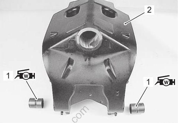
- Insert PORT and STBD bushings (1) into the swivel bracket (2).
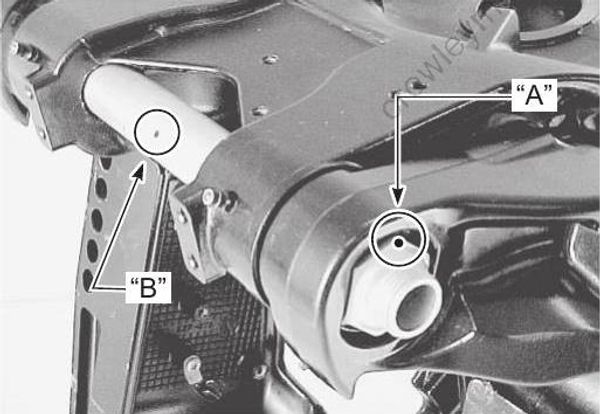
- Assemble PORT clamp bracket (3), washer (4), clamp bracket shaft (5) and swivel bracket (2).
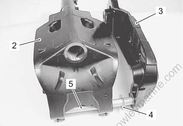
For proper operation of the tilt limit device, install the clamp bracket shaft to the port clamp bracket so the red paint mark “A” on the hex section and the cam holder location hole “B” on the clamp bracket shaft are positioned as shown in the figure.
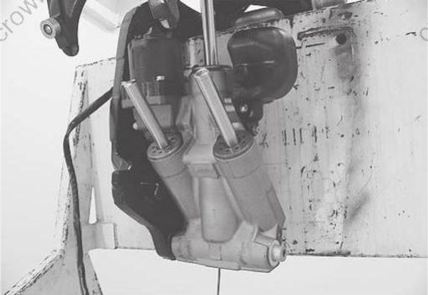
- Install PTT unit assembly.
Refer to “Power Trim and Tilt Unit Removal and Installation” in Section 2B (Page 2B-14).
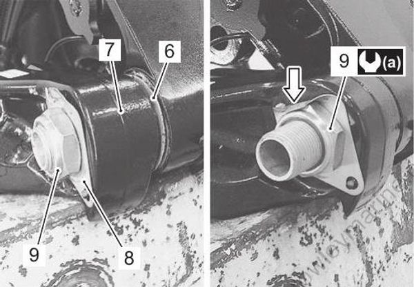
- Install washer (6), STBD clamp bracket (7), lock washer (8) and clamp bracket shaft nut (9), then tighten clamp bracket shaft nut to specified torque.
Tightening torque
Clamp bracket shaft nut (a): 43 N·m (4.3 kgf-m, 31.0 lbf-ft)
- After tightening clamp bracket shaft nut to specified torque, bend lock washer edge toward nut to secure nut.
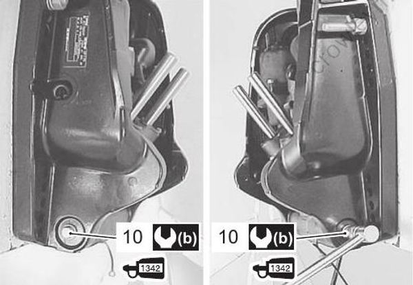
- Tighten two PTT unit retaining bolts (10), pre-coated with thread lock, to specified torque.
Thread lock cement 99000–32050 (SUZUKI Thread Lock 1342 (50 g))
Tightening torque
PTT retaining bolt (b): 60 N·m (6.0 kgf-m, 43.5 lbf- ft)
Tilt Limit Device
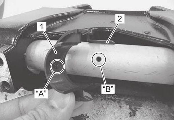
- Install the lower cam holder (1) engaging its locating pin “A” with the clamp bracket shaft hole “B”, then install the upper cam holder (2).
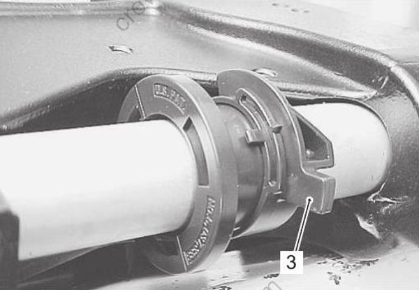
- Install tilt limit switch cam (3).
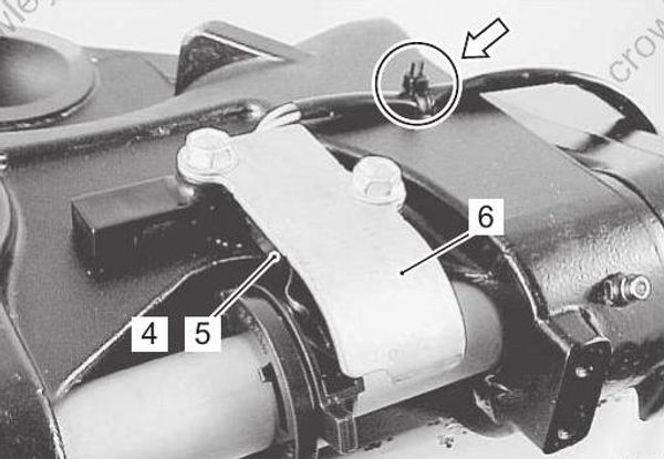
Install tilt limit switch (4), switch holder (5) and switch cover (6), then secure with bolts.
Secure switch lead wire with cable tie.
Steering Bracket
- Apply water resistant grease to steering bracket shaft.
Grease 99000–25350 (SUZUKI Water Resistant Grease EP2 (250 g))
Apply water resistant grease to bushings, oil seal lip and pilot shaft portion of steering bracket.
Install upper bushing (1) and washer (2) to swivel bracket.
Install lower bushing (3) and swivel bracket seal (4) to swivel bracket.
Install seal (4) with lip (spring side) facing downward.
- Install steering bracket (5) to swivel bracket.
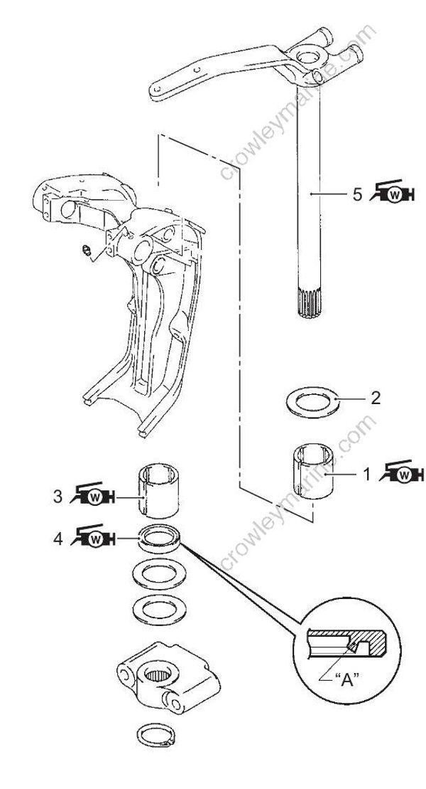
| 1. Upper bushing |
| 2. Washer |
| 3. Lower bushing |
| 4. Swivel bracket seal |
| 5. Steering bracket |
| “A”: Seal lip |
Lower Mount Bracket
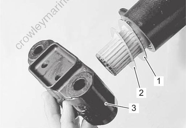
- Install washer (1) and shim (2), and then slide the lower mount bracket (3) upward on the splines until it contacts the shim.
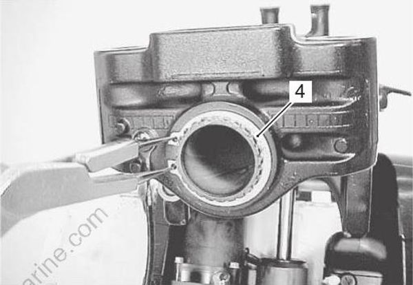
- Install circlip (4) to retain lower mount bracket.
Bonding Wire
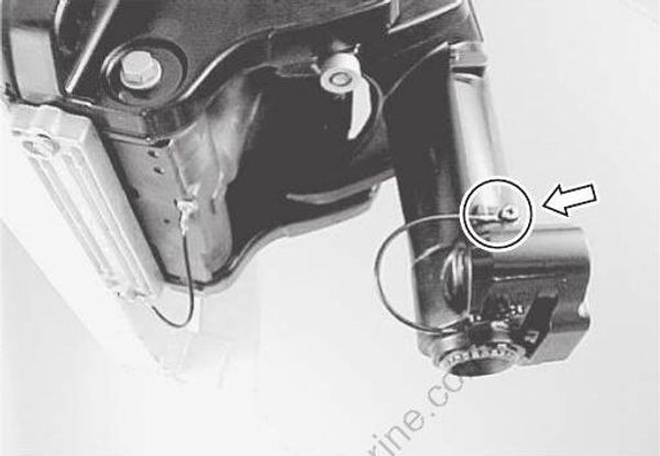
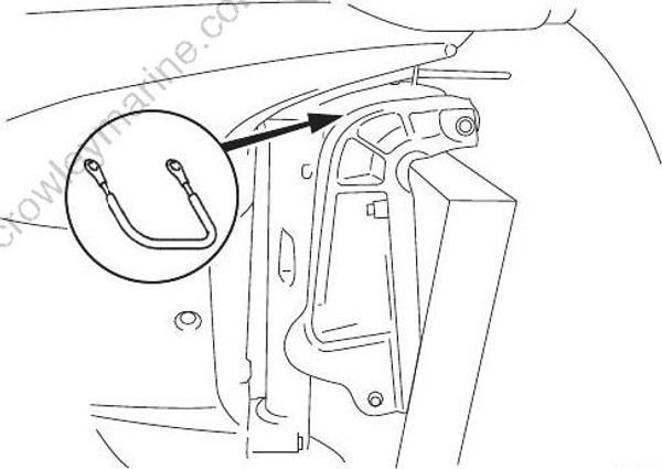
Reattach bonding wire to swivel bracket and tighten screw securely.
Lubrication
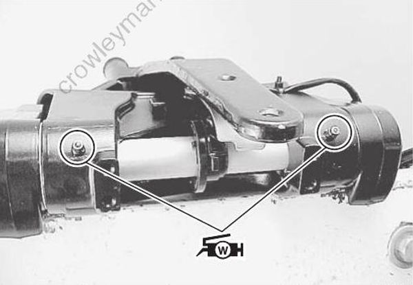
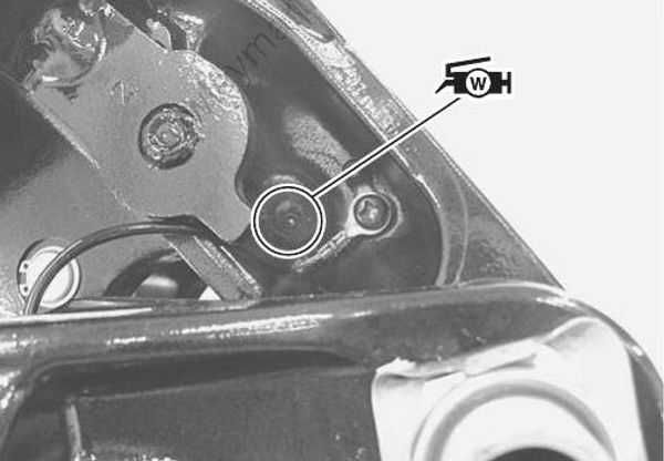
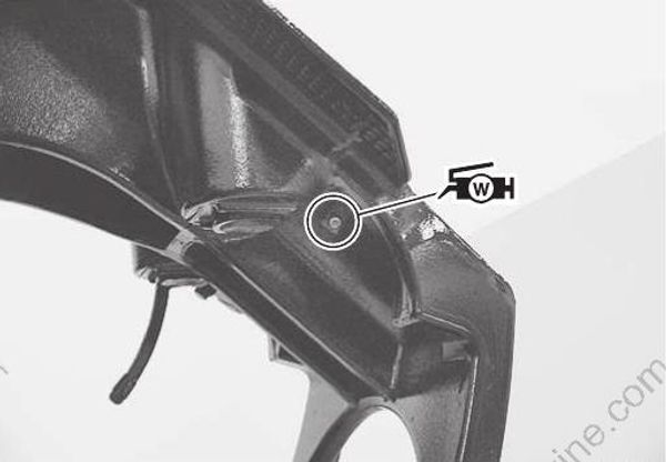
After completing reassembly of the mid unit, apply water resistant grease through each grease nipple.
Grease 99000–25350 (SUZUKI Water Resistant Grease EP2 (250 g))
Clamp / Swivel / Steering Brackets Related Components Inspection
Refer to “Clamp / Swivel / Steering Brackets Disassembly” (Page 2A-19) and “Clamp / Swivel / Steering Brackets Assembly” (Page 2A-21).
If any component is found to be excessively worn, cracked, defective or damaged in any way, it must be replaced.
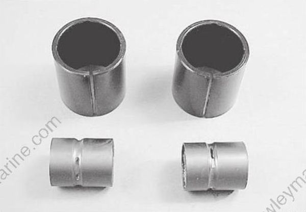
Bushings
Check all bushings. If excessive wear or other damage is found, replace bushing. If bushing fit is loose when installing, replace bushing.
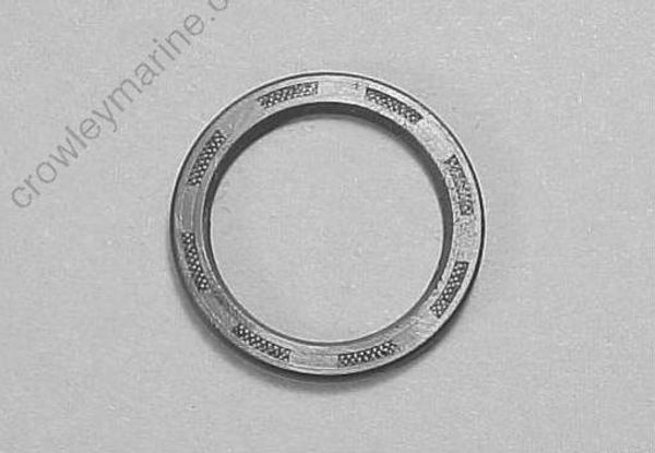
Oil Seal
Check swivel bracket seal.
If excessive wear or other damage is found, replace seal.
Clamp Bracket Shaft
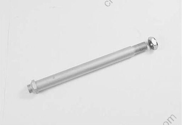
Check clamp bracket shaft.
If clamp bracket shaft is bent or twisted, replace shaft.
Bracket
Check clamp brackets, steering bracket and swivel bracket.
If cracks or other damage is found, replace bracket (s).