

Fuel System
Precautions
Precautions on Fuel System Service
Service operation of any type performed on the fuel system involves a risk of fire and injury if proper precautions are not taken.
Be sure to take the following precautions when working around gasoline or servicing the fuel system.
• Disconnect battery cables except when battery power is required for servicing/inspection.
• Keep the working area well ventilated and away from open flame (such as gas heater) or sparks.
• Do not smoke or allow anyone else to smoke near the working areas. Post a “NO SMOKING” sign.
• Keep a fully charged CO2 fire extinguisher readily available for use.
• Always use appropriate safety equipment and wear safety glasses when working around a pressurized fuel system.
• To avoid potential fire hazards, do not allow fuel to spill on hot engine parts or on operating electrical components.
• Wipe up fuel spills immediately.
• Before loosening or disconnecting the fuel feed line, be sure to relieve the fuel system of fuel pressure by following the fuel pressure relief procedure.
• When disconnecting a fitting on the fuel line, cover the fitting with a shop cloth to soak up the small amount of fuel that may flow out from the disconnected fuel line. Put the used cloth in an approved container.
• Since fuel hose connections vary with the pipe type, connect and clamp each hose using the correct method for each specific connection. After connecting a hose, check that there is no twist or kink in the hose.
• When installing hose clamps, position tabs to avoid contact with other parts.
• Be sure hoses do not contact rods, levers or other components with engine either operating or at rest.
General Description
Electronic Fuel Injection System Description
The fuel injection system used by the DF200AP is a speed-density, multi-point, sequential, electronic fuel injection type.
The fuel injection system is composed of the fuel line components, air intake components, and components for system control (ECM, sensors, switches, etc.).
Fuel Injection Control System Outline
Sensors are mounted at precise locations on the motor to monitor the current conditions of engine operation and send signals to the ECM.
Based on these signals, the ECM determines the optimum fuel injection time duration (fuel amount), fuel injection timing (multi-point sequential timing) and controls the injector operating signals accordingly.
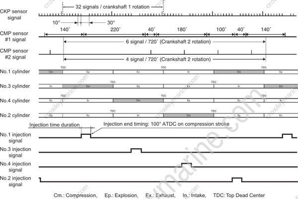
In regards to fuel injection timing, the fuel injection end timing is set depending on engine rpm. The ECM calculates the amount of fuel injection based on the engines operating conditions, and determines the fuel injection start timing. In the injection timing chart below, the injection end timing is set at 100° ATDC on the compression stroke.
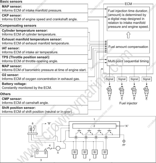
- ECM
- CPU
- Battery
- 30 A fuse
- Main switch
- ECM main relay
- Fuel injector
“A”: Sensor/switch signal input
“B”: To fuse box
Fuel Injection Timing Chart
Fuel Injection Control Mode
Before start:
When the main switch is turned “ON”, the ECM receives a MAP sensor signal, indicating the static barometric pressure of the intake manifold. This signal is used to compensate the fuel injection map.
When cranking:
Fuel is injected in each cylinders according to the “Start up mode” map which is based on the cylinder temperature and intake air temperature (Sequential injection).
After start (Fast-idle function):
The fuel injection amount is controlled so that the engine rpm stays within the fast idle speed map until the cylinder temperature reaches normal operating temperature.
When idling / trolling:
The fuel injection amount is controlled to maintain a stable engine speed at the specified idle/trolling rpm.
When running (normal operation):
ECM calculates the target air/fuel ratio on basis of signals from O2 sensor, CKP sensor, MAP sensor, etc. ECM compensates the basic fuel injection amount so as to obtain the calculated air/fuel ratio.
When accelerating:
The fuel injection amount is controlled to increase.
When decelerating:
The fuel injection amount is controlled to decrease.
Fuel Delivery System Component Description
The fuel delivery system is composed of the low pressure fuel line components (fuel tank, filter, pump etc.), fuel vapor separator, high pressure fuel pump, high pressure fuel filter, fuel pressure regulator (located in the fuel vapor separator), delivery pipe, fuel injector and hoses.
Fuel is supplied through the primer bulb, low pressure fuel filter, and low pressure fuel pump to the fuel vapor separator.
Fuel flow from the fuel vapor separator is pressurized by the high pressure fuel pump and supplied through the high pressure fuel filter and fuel delivery pipe to the fuel injectors.
The pressure regulator maintains fuel pressure in the feed line between the high pressure fuel pump and fuel injector. This pressure, maintained at a constant level, is higher than the pressure in the vapor separator chamber.
When fuel feed line pressure exceeds vapor separator chamber pressure by more than approx. 250 kPa (2.55 kg/cm2, 36.3 psi), the valve in the fuel pressure regulator will open and return the excess fuel to the vapor separator chamber. Pressurized fuel enters into the intake ports through the fuel injector based on the sequential signals supplied from the ECM.
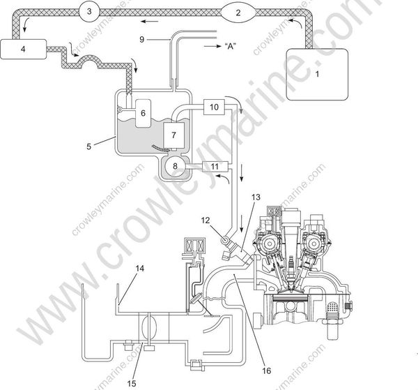
- Fuel tank
- Primer bulb
- Low pressure fuel filter
- Low pressure fuel pump
- Fuel vapor separator
- Float
- High pressure fuel pump
- Fuel pressure regulator
- Evaporation hose
- High pressure fuel filter
- Fuel cooler
- Fuel delivery pipe
- Fuel injector
- Air intake silencer case
- Electronic throttle body
- Intake manifold
“A”: To atmosphere
Low Pressure Fuel Pump
The low pressure fuel pump is operated by the plunger contacting the cam.
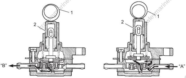
- Cam
- Plunger
“A”: Fuel in
“B”: Fuel out
Fuel Vapor Separator
The fuel vapor separator incorporates a float system that maintains a constant fuel level inside the separator chamber. As the fuel level decreases, fuel flows into the vapor separator from the low pressure fuel pump.
The function of this unit is to separate vapors from fuel delivered by the low pressure fuel pump or fuel returned from the fuel pressure regulator.
This vapor is routed through the evaporation hose connecting the vapor separator cover to atmosphere.
High Pressure Fuel Pump
The high pressure fuel pump is an “integral” type in which the pump mechanism is located within the fuel vapor separator.
To supply the optimum fuel amount, the pump is driven by the duty cycle signal from ECM.
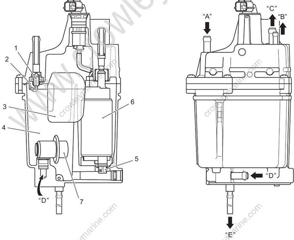
- Needle valve
- Valve seat
- Float
- Float chamber
- Suction filter
- High pressure fuel pump
- Fuel pressure regulator
“A”: Fuel inlet
“B”: Evaporation gas
“C”: Fuel outlet
“D”: Fuel return
“E”: Fuel drain
Fuel Pressure Regulator
The fuel pressure regulator is located in the fuel vapor separator.
The regulator’s function in the system is to maintain a constant fuel pressure relative to the injector while the engine is operating.
The regulator diaphragm chamber is open to the fuel vapor separator chamber to keep the pressure balanced.
Fuel pressure, adjusted by the regulator, is constantly maintained higher than the pressure in the fuel vapor separator chamber by approx. 250 kPa (2.55 kg/cm2, 36.3 psi).
By-pass fuel is returned to the fuel vapor separator chamber.
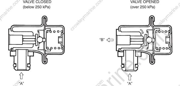
“A”: From fuel delivery line
“B”: To float chamber (Fuel return)
Fuel Injector
The fuel injector is an electromagnetic valve operated by a signal from the ECM.
When the injection signal is supplied to the fuel injector, the solenoid coil is energized pulling up the plunger. This opens the injector valve and injects fuel.
Because the fuel pressure is kept constant, the amount of fuel injected is determined by the amount of time (duration) the valve is open.
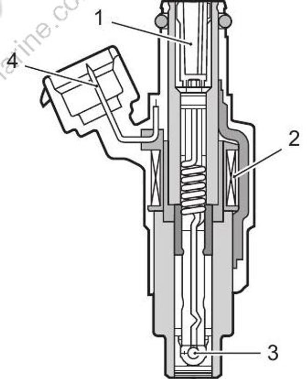
- Filter
- Solenoid coil
- Ball valve
- Terminal
High Pressure Fuel Pump Control System Description
To supply the optimum fuel amount, the ECM controls the fuel pump drive duty cycle, a repeated ON/OFF signal, at a specified rate (1 000 times a second).
Based on engine speed and battery voltage, the ECM determines the optimum duty (repeating “ON” time rate within a cycle) and sends this signal to the fuel pump.
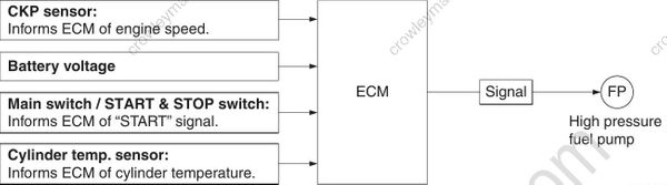
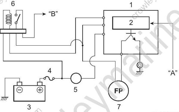
- ECM
- CPU
- Battery
- 30 A fuse
- Main switch
- ECM main relay
- High pressure fuel pump
“A”: Sensor/switch signal input
“B”: To fuse box
Duty cycle signal for fuel pump (example: 80% duty)
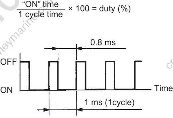
Control Modes
Before start:
For 3 seconds after the main switch is turned “ON”, the pump is controlled to operate at 100% duty in order to initially pressurize the high pressure line.
When cranking:
The pump is controlled to operate at 50 – 100% duty. Duty change depends on cylinder temperature.
When running (normal operation):
The pump is controlled to operate at 50 – 100% duty based on the current engine speed and battery voltage.
Air Intake Components Description
The main components of air intake system are silencer case, electronic throttle body assembly and intake manifold. Air, after entering through the silencer case, passes through the throttle body and flows into the surge tank where it is then distributed to the cylinder intake manifold.
Intake manifold pressure, monitored by the MAP sensor, is an indirect measure of the intake air amount.
Electronic throttle system is not equipped with IAC valve for idle speed control.
Idle speed is controlled by the throttle actuator which open/close the throttle valve.
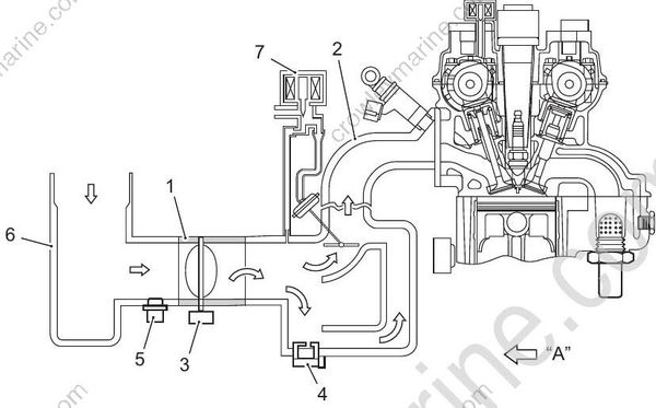
- Electronic throttle body
- Intake manifold
- Throttle actuator/TPS
- MAP sensor
- IAT sensor
- Air intake silencer case
- VSV
“A”: Air flow
Electronic Throttle Body
- The electronic throttle body is located on top of the intake manifold assembly.
- The throttle body assembly consists of the main bore, throttle valve, TPS (Throttle position sensor) and throttle motor.
- The throttle body adjusts the intake air amount by the throttle actuator which open/close the throttle valve.
Do not try to adjust or remove any of the electronic throttle body component parts (throttle position sensor, throttle valve, throttle actuator, etc.). These components have been factory adjusted to precise specifications.
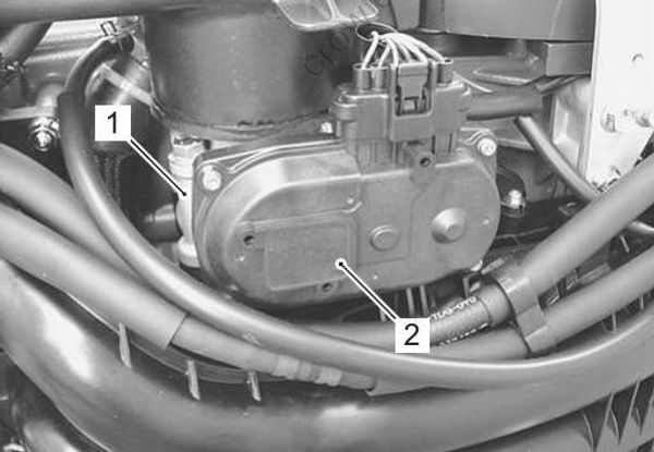
- Electronic throttle body
- Throttle actuator and TPS
Electronic Throttle System Description
Outline
The electronic throttle system consists of electronic throttle body assembly, lever position sensor assembly, ECM, BCM and throttle actuator control relay. Among them, assembly components are as follows.
- Electronic throttle body assembly: throttle valve, throttle actuator, two throttle position sensors.
- Lever position sensor assembly: remote control lever, two lever position sensors.
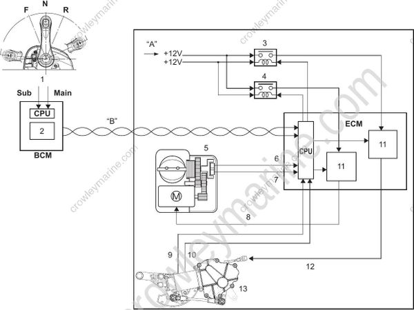
- LPS signal (main and sub)
- CAN driver
- ESA motor relay
- ETV motor relay
- Electronic throttle body
- TPS signal (main)
- TPS signal (sub)
- ETV motor operating signal
- Shift position sensor signal
- Neutral switch signal
- Motor driver
- ESA motor operating signal
- ESA
A”: From main relay
“B”: CAN communication
Operation
- ECM detects the remote control lever position by the voltage signal supplied from the lever position sensor that is built in the remote control box. The lever position sensor signal is inputted to ECM through BCM.
ECM calculates and determines the optimum throttle valve opening on the basis of detected target throttle valve opening (lever position voltage signal), current throttle valve opening (actual throttle valve opening) and the current engine condition. It then drives the motor built in the throttle body to open the throttle valve.
The throttle valve opening is sensed by the throttle position sensor and is supplied to ECM as feedback. - The idling/trolling speed control is performed by the electronic throttle system and the throttle valve is opened/ closed by means of the throttle actuator. There is no IAC valve for this purpose.
- To enhance reliability, a dual system (main and sub) is used for monitoring failures of throttle and lever position sensor systems.
- When a failure is detected in the throttle position sensor, this system turns off the throttle motor relay, then the throttle valve is locked by the return spring into the default opening (approx. 9.5° of mechanical opening from complete close position).
- When the lever position sensor failure is detected, the throttle valve is locked into the complete close position.
- When the remote control box is replaced, the setting change should be performed using SDS Ver. 8.
- When ECM is replaced, BCM initialization and the system calibration should be performed using SDS Ver. 8.
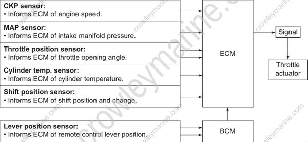
Control Mode
On the basis of lever position sensor voltage signal, throttle position sensor signal and the engine condition, a calculation is operated for driving throttle motor, then the throttle opening is controlled. According to the engine condition, the following controls are performed.
Start-up control
The throttle valve opening at start-up is predetermined in relation to the cylinder wall temperature. Therefore, according to the engine temperature at start-up, the throttle valve is opened slightly to supply optimum intake air for improving start ability.
For improved starting, the lower the cylinder wall temperature, the wider the throttle valve opening.
Normal control
The throttle valve opening is determined according to the conditions such as cylinder wall temperature, shift position, lever position, etc.
(Compensations)
– Feedback compensation
If the actual engine speed deviates from the target engine speed for more than a predetermined time, this compensation is designed to adjust the speed close to the target. – Shift compensation
According to the condition of shift transition (F↔N↔R), the engine speed is compensated. – -–Deceleration control
During deceleration, the throttle valve is opened by a certain amount for increased air intake to prevent the engine speed from falling to quickly resulting in engine stalling.
Fail safe control
– When a failure is detected in the throttle position sensor, this system turns off the throttle motor relay, then the throttle valve is locked by the return spring into the default opening (approx. 9.5° of mechanical opening from complete close position).
– When the lever position sensor failure is detected, the throttle valve is locked into the complete close position. The operation of fail safe control depends on the detected diagnosis code.
Fully closed position learning
When the main switch is turned OFF, the throttle valve once returns to the fully closed position, then opens to the fully open position and thereafter closes to the default position.
Diagnostic Information and Procedures
Fuel Pressure Inspection
Gasoline is a flammable material that can cause fire hazard or burns. Before starting the following procedure, be sure to observe “Precautions on Fuel System Service” (Page 1G-1) in order to reduce the risk or fire and personal injury.
- Loosen the three bolts and remove the fuel hose guard (1).
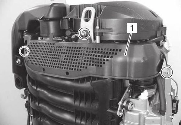
Relieve fuel pressure in fuel feed line.
Refer to “Fuel Pressure Relief Procedure” (Page 1G 16).Remove ring gear cover and air intake silencer case (2).
Refer to “Air Intake Silencer Case Removal and Installation” in Section 1D (Page 1D-2).
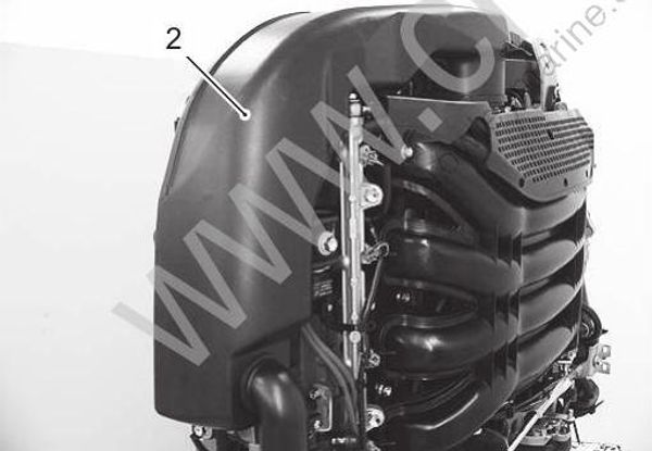
- Loosen the clamp and place a large cloth over the end of fuel feed hose (3).
Disconnect high pressure fuel feed hose (3) from fuel delivery pipe upper union (4).
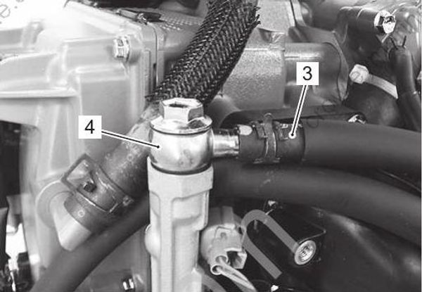
- Connect special tools (pressure gauge, pressure hose and pressure joint) between fuel feed hose and fuel delivery pipe upper union as shown in figure. Clamp the hose securely to ensure that no leaks occur during checking.
Gasoline is a flammable material that can cause fire hazard or burns. A small amount of fuel may be released when the fuel feed hose is disconnected. Place container under the fuel feed hose or fuel delivery pipe with a shop cloth so that the released fuel is caught in the container or absorbed by the cloth. Place the fuel soaked cloth in an approved container.
Special tool
(A): 09912–58442 (Fuel pressure gauge)
(B): 09912–58432 (Fuel pressure hose)
(C): 09912–58490 (3-way joint & hose)
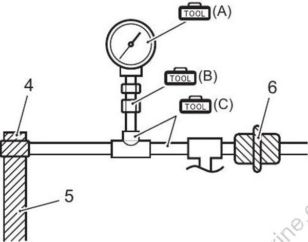
- Delivery pipe upper union
- Fuel delivery pipe
- High pressure fuel filter
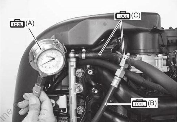
Reinstall ring gear cover and air intake silencer case. Refer to “Air Intake Silencer Case Removal and Installation” in Section 1D (Page 1D-2).
Ensure the emergency stop switch lock plate is in place.
Shift into neutral position.Squeeze fuel primer bulb until you feel resistance.
Turn main switch to “ON” for 3 seconds (to operate the fuel pump), then turn it “OFF”.
Repeat this (“ON” and “OFF”) procedure 3 or 4 times to pressurize the fuel system and then check the fuel pressure.
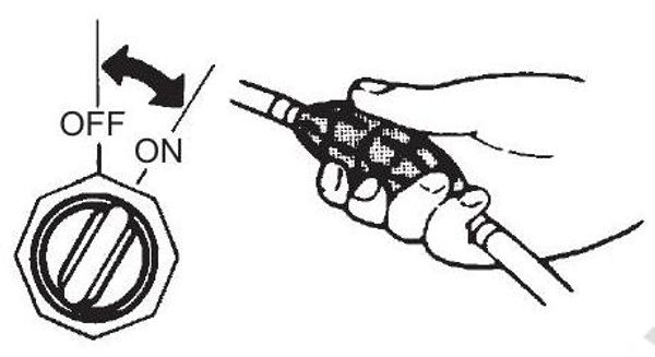
Check for any signs of fuel leakage.
Measure fuel pressure at cranking or idle speed operation.
Fuel pressure
Standard: Approx. 255 kPa (2.55 kg/cm², 36.3 psi.)
Stop engine and wait 5 minutes.
Check the residual fuel pressure in line.Residual fuel pressure
Standard: 200 kPa (2.0 kg/cm², 28.4 psi.) or more
Gasoline is a flammable material that can cause fire hazard or burns. The fuel feed line is under high fuel pressure, make sure to release fuel pressure according to the fuel pressure relief procedures mentioned earlier. Use the following procedures to remove the fuel pressure gauge.
• Place a container under the joint to catch the fuel.
• Cover the joint with rag and loosen joint nut slowly to gradually release any residual fuel pressure.
- After checking fuel pressure, remove fuel pressure gauge.
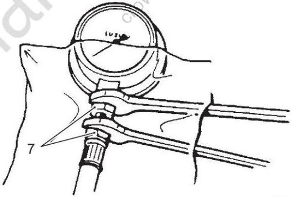
- Joint nut
Reconnect fuel line.
With the engine not running and main switch “ON”, check the fuel system for leaks.
Reinstall fuel hose guard, and tighten the bolts securely.
Fuel System Diagnosis
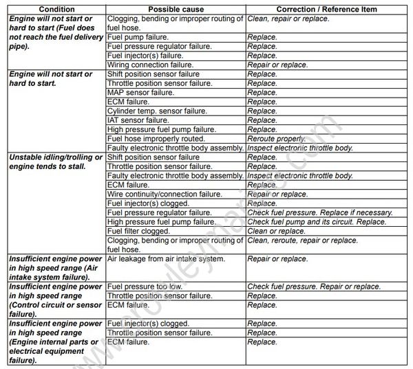
Fuel Injection System Troubleshooting
Before starting the troubleshooting, make sure that:
- There is no self-diagnostic code indication.
- Emergency stop switch plate is set in place.
Step 1
Check fuel injector operating sound.
- Check each injector for operating sound at engine cranking. ((Page 1G-24))
Do all four injectors make operating sound?
Yes Fuel injector circuit is in good condition.
No Go to step 2.
Step 2
Check fuel injector resistance.
- Turn main switch to “OFF”, disconnect connectors from fuel injectors.
- Check for proper connection to fuel injector at each terminal.
- If good condition, check all fuel injector for resistance. ((Page 1G-24))
- *Are all injectors in good condition?**
Yes Go to step 3.
No Faulty fuel injector.
Step 3
Check fuel injector power supply.
- Measure voltage between each “Gr” wire terminal of fuel injector connector and engine body ground with main switch turned “ON”.
Is voltage 10 – 14 V?
Yes Go to step 4.
No * “Gr” wire open or shorted.
* If it is in good condition, check ECM power source and ground circuit.
Step 4
Check Wire circuit.
Turn “OFF” main switch.
Disconnect connector from ECM.
Measure resistance between each “O/B”, “B/Br”, “R/ W”, “Lg” wire terminal of the fuel injector connector and body ground.
*Is resistance infinity?**
Yes Go to step 5.
No “O/B”, “B/Br”, “R/W”, and/or “Lg” wire(s) are shorted to ground.
Step 5
Check Wire circuit.
- Connect connector to ECM.
- Measure voltage between each “O/B”, “B/Br”, “R/W”, “Lg” wire terminal of fuel injector connector and body ground with main switch turned “ON”.
Is voltage 0 V?
Yes Go to step 6.
No “O/B”, “B/Br”, “R/W”, and/or “Lg” wire(s) are shorted to power supply circuit.
Step 6
Check fuel injector operating signal.
- Connect connectors to each fuel injector and ECM with main switch turned “OFF”.
- Measure fuel injector operating signal between each “55”, “56”, “79”, “54” terminal of ECM and body ground. ((Page 1G-25))
Is voltage 6 – 10 V or over?
Yes If check result is satisfactory, substitute a known-good ECM and recheck.
No “O/B”, “B/Br”, “R/W”, and/or “Lg” wire(s) are open circuit.
Service Instructions
Fuel Pressure Relief Procedure
After making sure that engine is cold, relieve fuel pressure as follows:
Turn the main switch “OFF”.
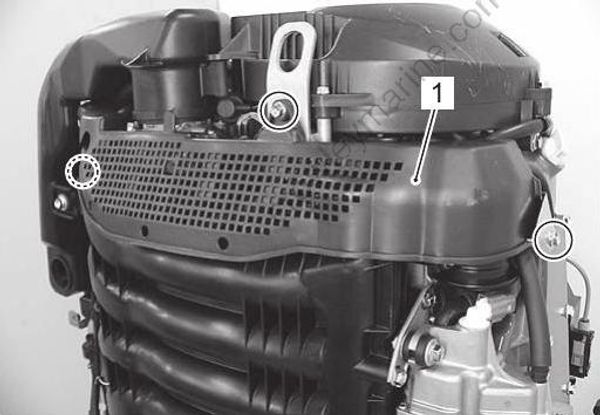
Loosen the three bolts and remove the fuel hose guard (1).
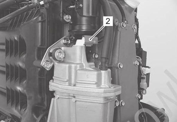
- Disconnect the high pressure fuel pump lead wire connector (2) at high pressure fuel pump.
- Disconnect the ignition coil primary lead wire connectors (3) from all of the ignition coils.
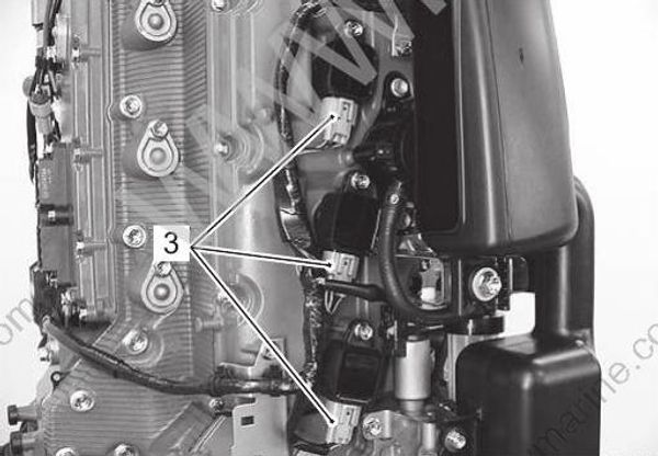
Crank the engine 5 – 10 times (3 seconds each time) to dissipate the fuel pressure in lines.
Make sure fuel pressure has been relieved by pinching the high pressure fuel hose (4) between finger tips (the line should feel soft, without pressure).
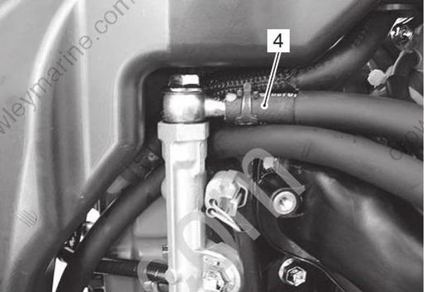
- Upon completion of servicing, connect the ignition coil primary lead wires and high pressure fuel pump lead wire.
Fuel Line Removal and Installation
Pay special attention to the following points when removing or installing fuel hoses.
Gasoline is a flammable material that can cause fire hazard or burns. Before starting the following procedure, be sure to observe “Precautions on Fuel System Service” (Page 1G-1) in order to reduce the risk or fire and personal injury.
The fuel feed line is under high pressure, use special care when servicing it.
Spilled gasoline should be wiped off immediately.
Perform the following checks to ensure proper and safe operation of the repaired unit. – Check fuel hose routing.
Refer to “Fuel Hose Routing” in Section 4B (Page 4B-1).
– Check for fuel leakage.
Refer to “Fuel Leakage Check Procedure” (Page 1G-17).
Fuel Line Inspection
Visually inspect fuel lines for evidence of fuel leakage, cracking, deterioration, or damage. Make sure all clamps are secure. Replace parts as needed.
Fuel Leakage Check Procedure
After performing any fuel system service, always be sure there is no fuel leakage by checking as follows.
Squeeze fuel primer bulb until you feel resistance.
Shift into “Neutral” position.
Ensure emergency stop switch lock plate is in place. 4) Turn main switch “ON” for 3 seconds (to operate fuel pump), then turn it “OFF”.
Repeat this (“ON” and “OFF”) procedure 3 or 4 times to pressurize the fuel system.Once pressurized, check all connections and components for any signs of leakage.
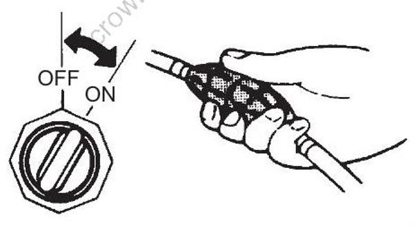
Inspection of Fuel Hose Connections
Note that the fuel hose connection varies with each type of pipe. Be sure to connect and clamp each hose correctly by referring to the figure.
- For type “A” (short barbed end) pipe, the hose must completely cover pipe.
Type “A”
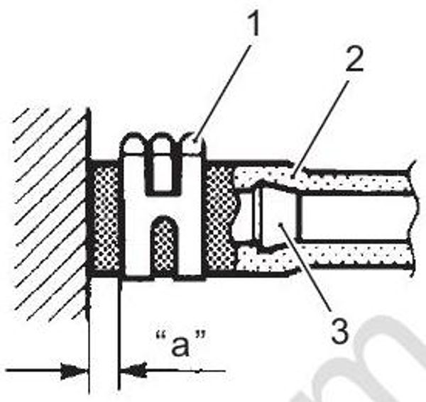
- Clamp (Clip)
- Hose
- Joint pipe
“a”: 3 – 7 mm (0.1 – 0.3 in)
- For type “B” (bent end) pipe, hose must cover the straight part of pipe by 20 – 30 mm (0.8 – 1.2 in.).
Type “B”
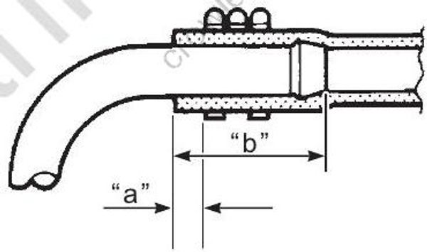
“a”: 3 – 7 mm (0.1 – 0.3 in)
“b”: 20 – 30 mm (0.8 – 1.2 in)
- For type “C” pipe, hose must fit up against the flanged part of pipe.
Type “C”
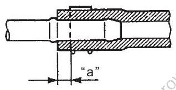
“a”: 3 – 7 mm (0.1 – 0.3 in)
- For type “D” pipe, the hose must cover the pipe by 20 – 30 mm (0.8 – 1.2 in.).
Type “D”
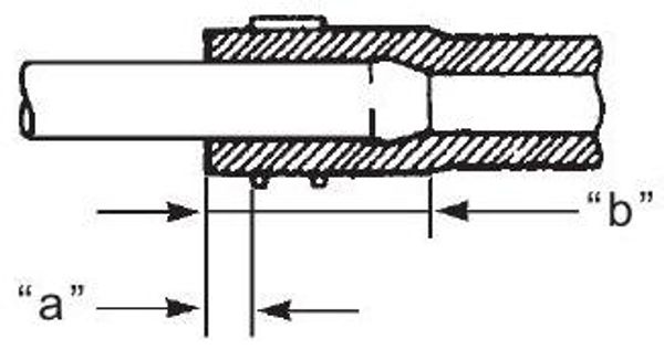
“a”: 3 – 7 mm (0.1 – 0.3 in)
“b”: 20 – 30 mm (0.8 – 1.2 in)
High Pressure Fuel Pump Operating Sound Inspection
Install the emergency stop switch lock plate into position.
Shift into neutral.
Turn main switch “ON” and check for fuel pump operating sound.
Fuel pump operating sound is low because the pump is inside the fuel vapor separator. If you cannot hear the pump sound clearly, use a sound scope or long blade screw driver.
Fuel pump operating sound
Sounds for approx. 3 seconds only
(each time the main switch is turned to the “ON” position)
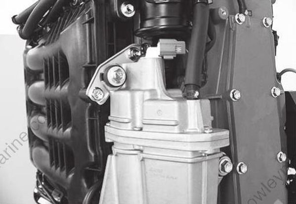
- If no pump operating sound is heard:
a) Turn main switch to the “OFF” position, check for contact failure in the lead wire connector.
b) Check that the drive voltage is outputting from the ECM and no abnormal conditions exist in the engine main wiring harness. c) If inspection in steps “a” and “b” are OK, replace the high pressure fuel pump.
Fuel Vapor Separator Removal and Installation
Removal
Gasoline is a flammable material that can cause fire hazard or burns. Before starting the following procedure, be sure to observe “Precautions on Fuel System Service” (Page 1G-1) in order to reduce the risk or fire and personal injury.
Relieve fuel pressure in fuel feed line.
Refer to “Fuel Pressure Relief Procedure” (Page 1G 16).Remove the lower side covers.
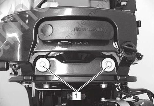
Refer to “Lower Side Cover Removal and Installation” in Section 2A (Page 2A-3).Remove the two bolts (1) securing front panel.
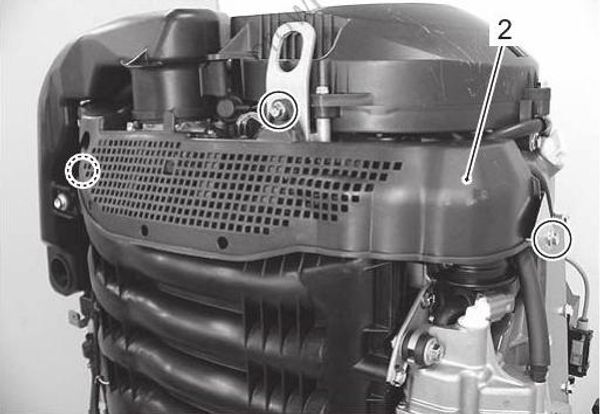
- Loosen the three bolts and remove the fuel hose guard (2).
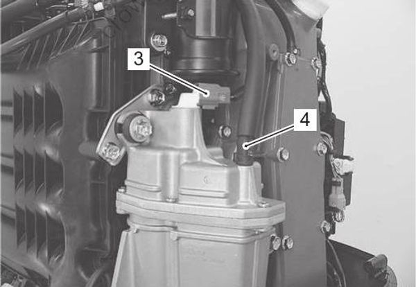
Disconnect high pressure fuel pump lead wire connector (3) at fuel pump.
Disconnect fuel hose (4) from fuel vapor separator.
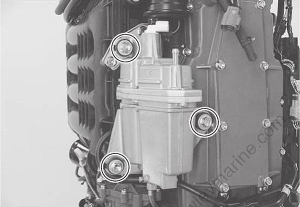
- Remove the three bolts securing fuel vapor separator.
- Disconnect fuel return hose (5) from fuel vapor separator.
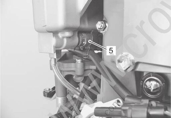
- Disconnect fuel hose (6) from high pressure fuel filter, then remove evaporation hose (7) from fuel vapor separator.
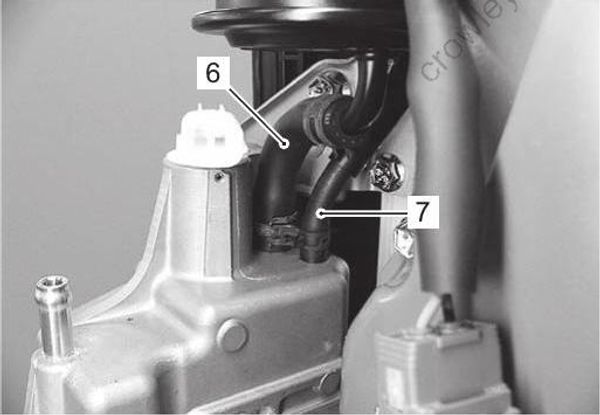
Installation
Installation is reverse order of removal with special attention to the following steps.
- Install the fuel drain hose (1) through the slit of side cover seal as shown in figure.
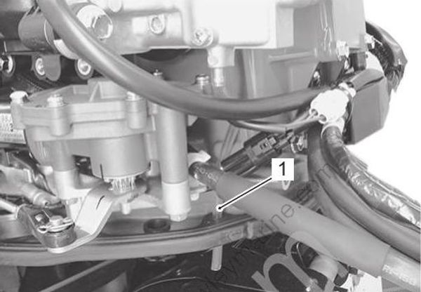
Check to ensure that all removed parts are back in place.
Check fuel hose routing.
Refer to “Fuel Hose Routing” in Section 4B (Page 4B 1).Check for fuel leakage.
Refer to “Fuel Leakage Check Procedure” (Page 1G 17).
Fuel Vapor Separator Disassembly and Assembly
Disassembly
Remove the fuel vapor separator.
Refer to “Fuel Vapor Separator Removal and Installation” (Page 1G-18).Remove five screws (1).
Remove separator cover (2) with high pressure fuel pump from separator case (3).
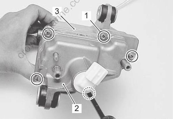
Remove the screw (4) securing float pin (5).
Remove the float (6), float pin (5) and needle valve (7).
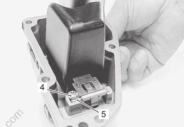
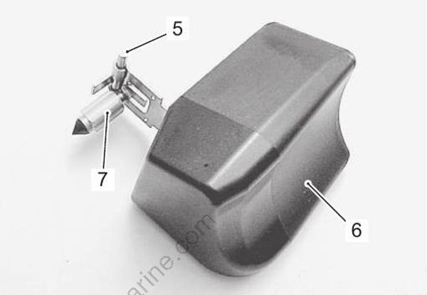
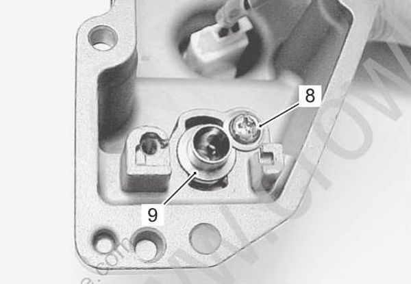
- Remove screw (8) and valve seat (9).
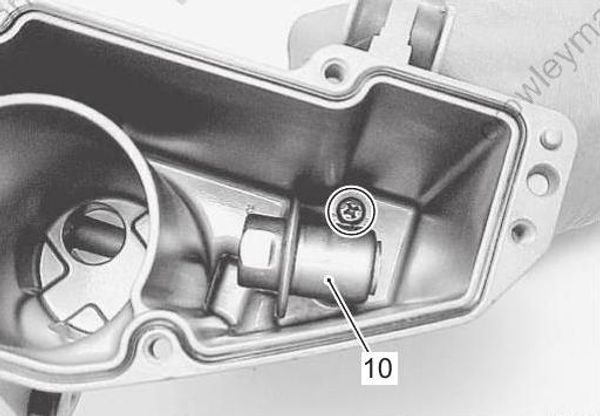
- Remove screw and fuel pressure regulator (10) from separator case.
- Remove suction filter (11).
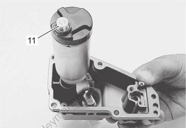
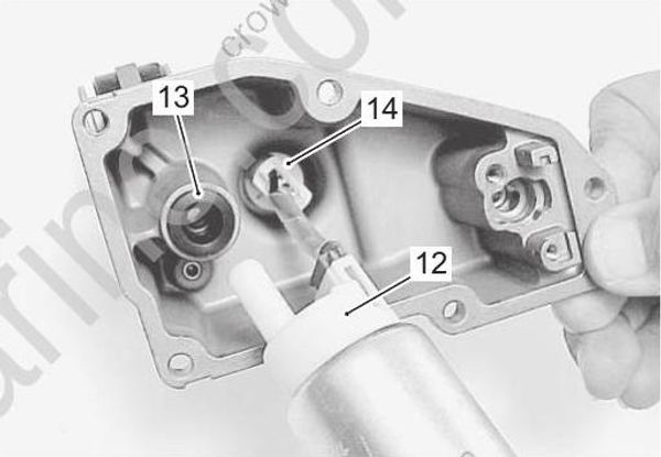
- Remove high pressure fuel pump (12) and grommet (13) from separator cover and then disconnect pump lead wire connector (14).
Assembly
Assembly is reverse order of disassembly with special attention to the following steps.
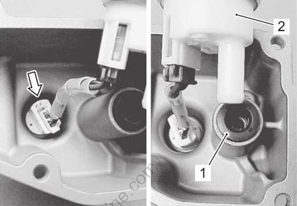
High pressure fuel pump
- Connect pump lead wire connector, then install grommet (1) and high pressure fuel pump (2).
Apply fuel to grommet before installing.
Float / Float pin
- Install float (1) and float pin (2), then secure float pin with screw (3).
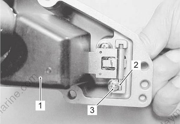
After assembling, check for smooth and free float movement.
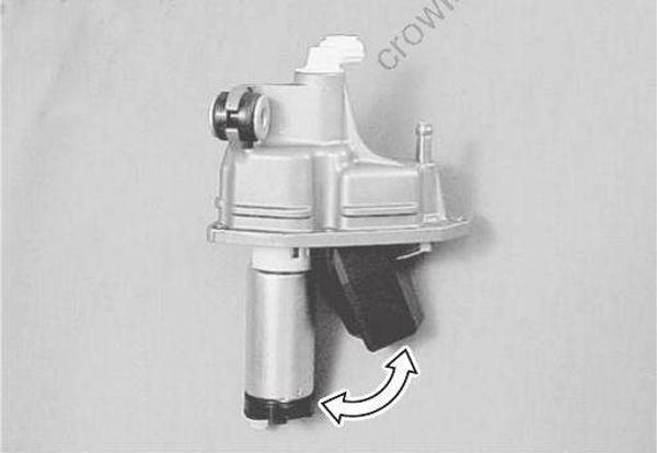
Checking float height
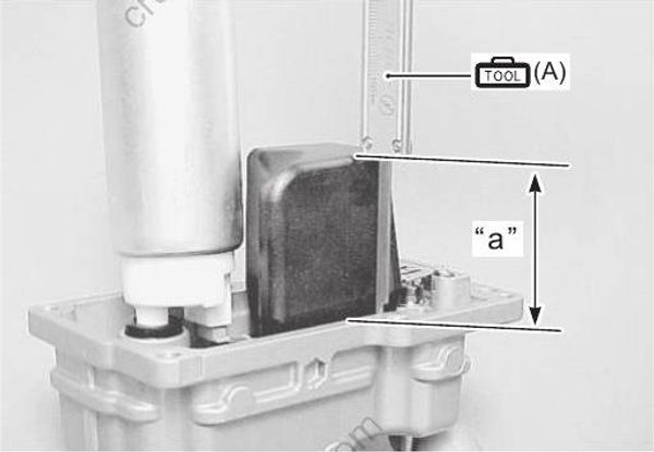
- Measure float height.
Special tool
(A): 09900–20101 (Vernier calipers (150 mm))
Float height “a”
Standard: 48 ± 3 mm (1.89 ± 0.12 in)
Make sure that the float weight is not applied to the needle valve.
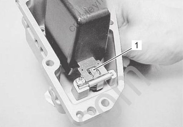
Setting float height
- To correct specification, bend only adjustment tab (1).
When adjusting the tab, do not bend to the point that it applies pressure to the needle and seat.
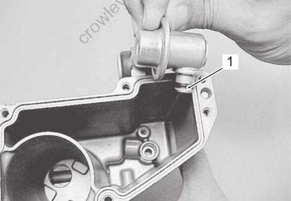
Fuel pressure regulator
- Install fuel pressure regulator and tighten screw securely.
Apply fuel to O-ring (1) before installing fuel pressure regulator.
Separator cover/Separator case
- Install seal ring (1), then apply SUZUKI Bond evenly to only the outside mating surface of the separator case as shown in figure.
Sealant 99000–31140 (SUZUKI Bond 1207B (100 g))
• Clean mating surfaces before applying bond.
• Do not apply bond to seal ring, groove and inside mating surface.
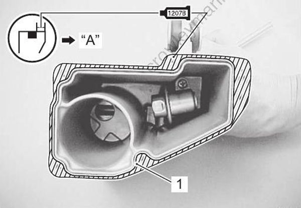
“A”: Outside
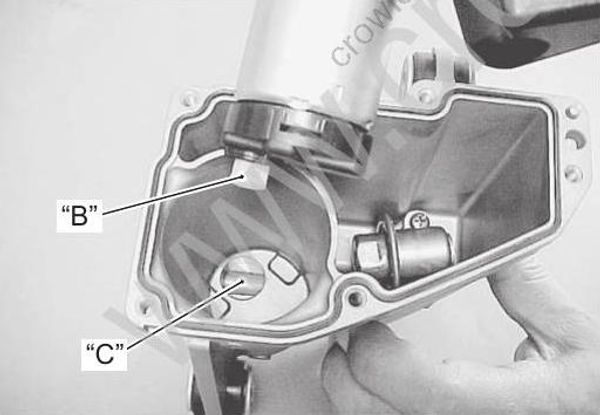
- Install separator case, then tighten screws securely.
When installing separator case, align suction hole “B” with hole “C” of separator case.
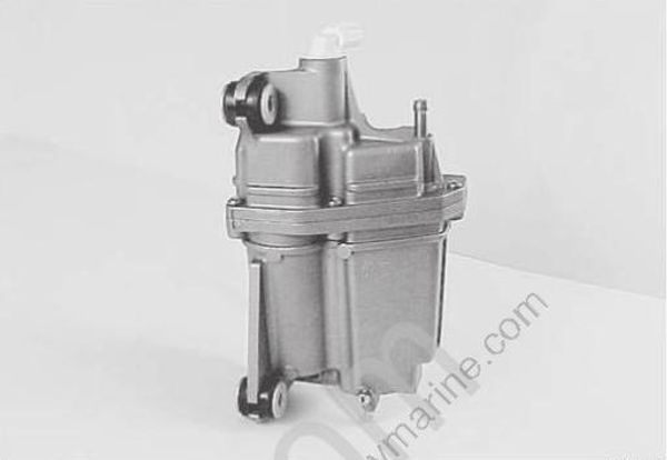
Separator cover and case are a set. If any repair is required on the cover or case, replace them as a fuel vapor separator assembly.
Final Assembly Check
- Check to ensure that all removed part are back in place.
- Check fuel hose routing.
Refer to “Fuel Hose Routing” in Section 4B (Page 4B 1). - Check for fuel leakage.
Refer to “Fuel Leakage Check Procedure” (Page 1G 17).
Inspection of Fuel Vapor Separator Component Parts
If cracks, excessive wear or other damage is found on any component, replace the component.
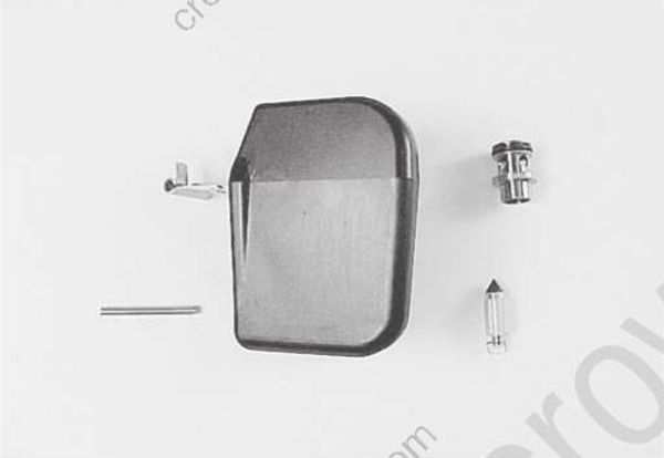
Needle Valve / Valve Seat
Inspect needle valve and valve seat for groove, other damage or dirt.
Replace or clean if necessary.
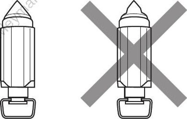
Float
Inspect the float for cracks or other damage. Replace if necessary.
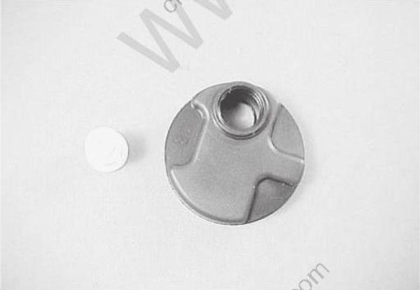
Filter
Inspect pump suction filter for clog or other damage. Replace or clean if necessary.
Fuel Pressure Regulator
Inspect fuel pressure regulator for damage or corrosion. Check fuel pressure regulator operation.
Special tool
(A): 09952–99320 (Hand air pump)
(B): 09940–44121 (Air pressure gauge)
(C): 09940–44130 (Attachment)
(D): 09912–58490 (3-way joint & hose)
- Connect special tools to inlet side of regulator as shown in figure.
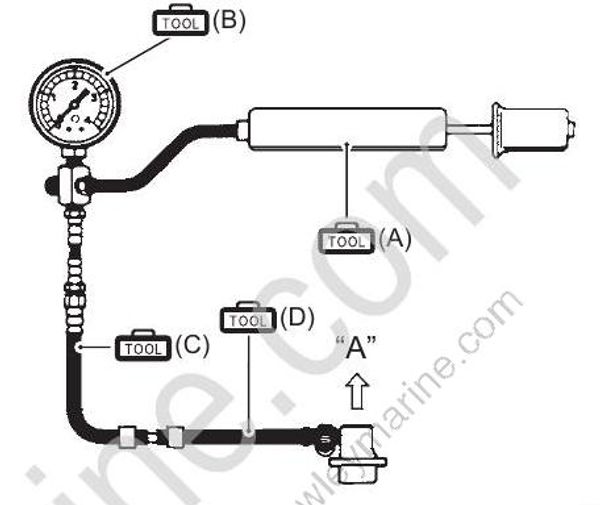
Pump air into regulator using pump until air is released through outlet side “A”.
Read pressure on gauge when air is released.
Regulator operating pressure:
240 – 270 kPa (2.4 – 2.7 kg/cm2, 34.1 – 38.4 psi)
If out of specification, replace regulator.
Fuel Injector Inspection with Injector in Place
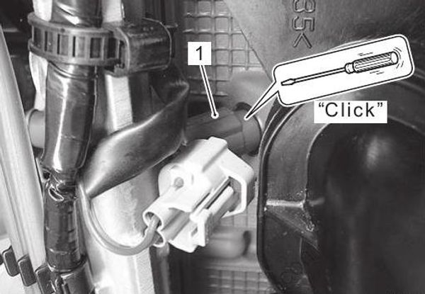
- Using a sound scope or equivalent, check the operating sound of the fuel injector when the engine is running or cranking.
Injector operating sound cycle should vary according to engine speed.
If no sound or an unusual sound is heard, check injector circuit (wire or connector) or injector.
- Injector body
Disconnect the lead wire connector from the fuel injector.
Connect a digital tester between the terminals of the injector and measure resistance.
If out of specification, replace the fuel injector.
Special tool
09900–25008 (Multi circuit tester set)
Tester knob indication
Resistance (Ω)
Fuel injector resistance
Standard: 10 – 14 Ω at 20 °C
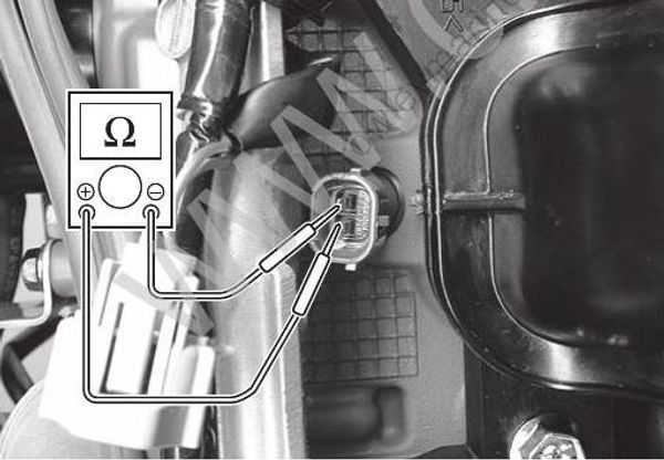
- Connect the lead wire connector to the fuel injector securely.
Individual Fuel Injector Operating Sound Inspection
Disconnect the ignition coil lead wire connectors from all of the ignition coils.
Disconnect the fuel injector lead wire connector and connect the test cord.
Special tool
(A): 09930–89260 (Injector test cord (A))
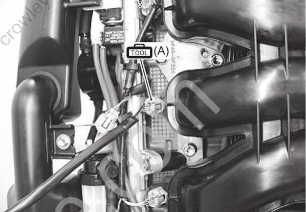
If battery power is applied too long in any of the following tests, the coil of the fuel injector may burn. Fuel injector test must be completed within few seconds to avoid burning of the coil.
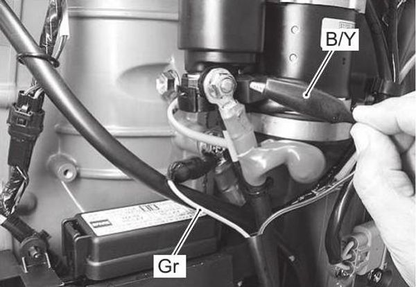
Connect Gr wire to body ground.
Momentarily touch the B/Y wire to the starter motor magnetic switch terminal “B” (connected to battery positive (+) terminal) and check for injector operating sound.
If out of specification, replace fuel injector.
Fuel injector operating sound
“Click”
Fuel Injector Operating Signal Inspection
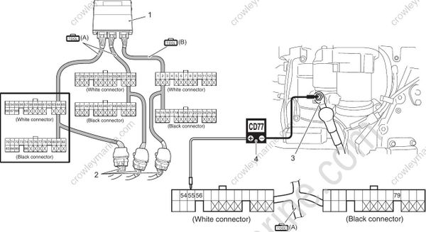
- ECM
- Wire harness
- Starter motor magnetic switch “B” terminal
- Stevens peak reading voltmeter CD-77
Special tool
(A): 09930–89340 (26-pin & 34-pin test cord)
(B): 09930–89850 (26-pin (B) test cord)
Stevens peak reading voltmeter CD-77
Tester knob indication
NEG 50
Disconnect all ignition coil connectors from the ignition coils.
Connect the test cord set between the ECM and wire harness as shown in figure, then turn main switch “ON”.
Connect the tester probe (“–”, Black) to the starter motor magnetic switch terminal “B” (connected to battery positive (+) terminal) as shown in figure.
Connect the tester probe (“+”, Red) to each terminal.
| Injector | Terminal | Wire color (Engine harness) |
|---|---|---|
| No.1 | 55 | O/B |
| No.2 | 56 | B/Br |
| No.3 | 79 | R/W |
| No.4 | 54 | Lg |
Crank the engine and measure the voltage.
If out of specification, inspect the related parts as described in “Fuel System Diagnostic Information/Fuel Injection System Troubleshooting”.
Refer to “Fuel System Diagnosis” (Page 1G-14) and “Fuel Injection System Troubleshooting” (Page 1G-15).Fuel injector operating signal
Standard: Approx. 6 – 10 V or over
Fuel Injector Removal and Installation
Removal
Relieve the fuel pressure in the fuel feed line according to “Fuel Pressure Relief Procedure”.
Refer to “Fuel Pressure Relief Procedure” (Page 1G 16).Remove the lower side covers.
Refer to “Lower Side Cover Removal and Installation” in Section 2A (Page 2A-3).Loosen the three bolts and remove fuel hose guard (1).
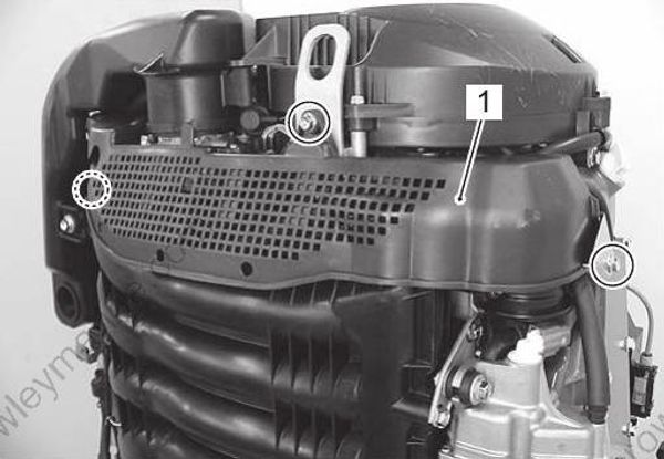
- Remove the air intake silencer case (2).
Refer to “Air Intake Silencer Case Removal and Installation” in Section 1D (Page 1D-2).
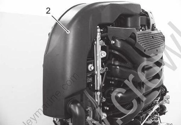
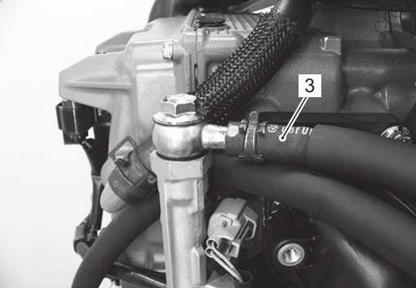
- Loosen the clamp and place a large cloth over the end of the fuel feed hose (3).
Slowly pull the fuel feed hose from the fuel delivery pipe.
Drain any excess fuel in the hose into a small container.
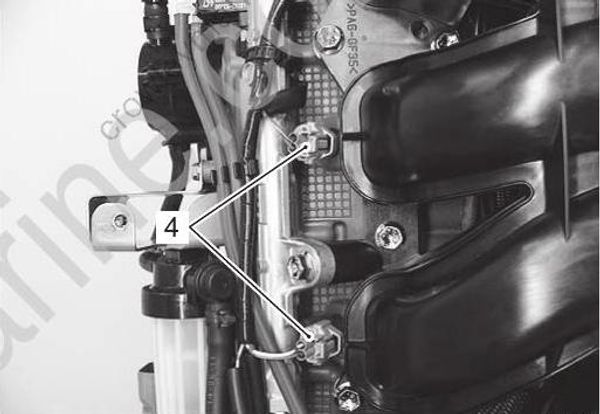
Disconnect the four fuel injector connectors (4).
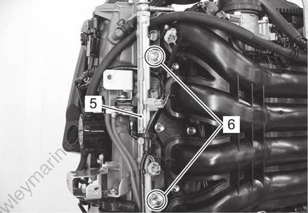
Remove two bolts (6) and fuel delivery pipe (5) (with fuel injectors).
Gasoline is a flammable material that can cause fire hazard or burns. A small amount of fuel may be released when the fuel injector is removed from delivery pipe. Place a shop cloth under fuel injector before removal to absorb any fuel released. Dispose of fuel soaked cloth in appropriate container.
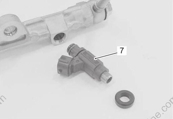
- Remove each fuel injector (7) from delivery pipe.
Installation
Installation is reverse order of removal with special attention to the following steps.
Failure to take proper precaution when reinstalling fuel injector can result in fuel leakage or damage. Do not re-use O-ring and cushion once removed. Always use new parts.
- Replace injector O-ring (1) with a new one using care to avoid nicks or cuts during installation.
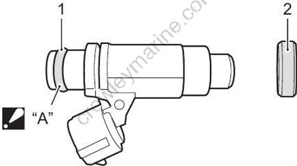
“A”: Apply fuel to O-ring
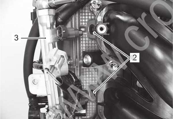
Replace the cushion (2) with a new one and install to the cylinder head.
Apply a thin coat of fuel to injector O-rings, then install the injectors into the delivery pipe (3) and cylinder head.
Make sure that the injectors rotate smoothly.
- Tighten delivery pipe bolts and make sure that injectors rotate smoothly.
Tightening torque
Fuel delivery pipe bolt (a): 23 N•m (2.3 kgf•m, 16.5 lbf•ft)
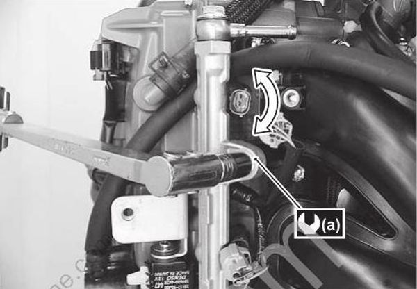
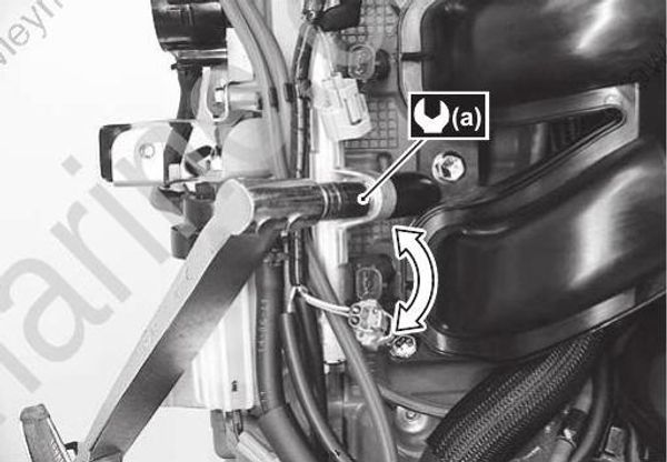
- Reconnect the fuel feed hose and fuel line securely.
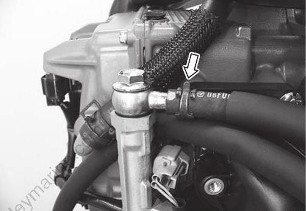
Connect the lead wire connector to the injectors securely.
Make sure the emergency stop switch lock plate is in place.
Shift into neutral position.Squeeze the fuel primer bulb until you feel resistance.
Turn main switch “ON” for 3 seconds (to operate fuel pump), then turn it “OFF”. Repeat this (ON and OFF) procedure 3 or 4 times to pressurize fuel system. Check for fuel leaks around fuel injectors.Check to ensure that all removed parts are back in place.
Low Pressure Fuel Pump Removal and Installation
Disassembling the low pressure fuel pump can lead to troubles. The low pressure fuel pump is a non-repairable component. Do not attempt to disassemble the low pressure fuel pump. It must be replaced as a complete unit if it is defective.
Removal
Remove the lower side covers.
Refer to “Lower Side Cover Removal and Installation” in Section 2A (Page 2A-3).Remove the resonator and air intake silencer case (1).
Refer to “Air Intake Silencer Case Removal and Installation” in Section 1D (Page 1D-2).
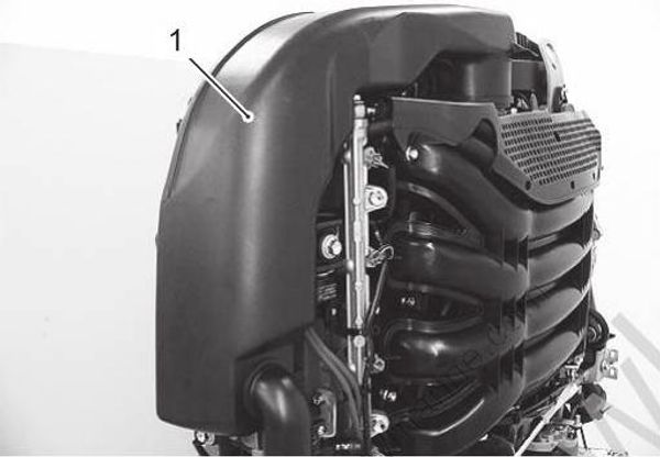
Disconnect the fuel inlet hose (2) and outlet hose (3) from low pressure fuel pump (4).
Remove two bolts (5) securing fuel pump.
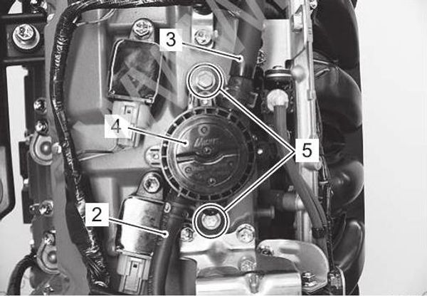
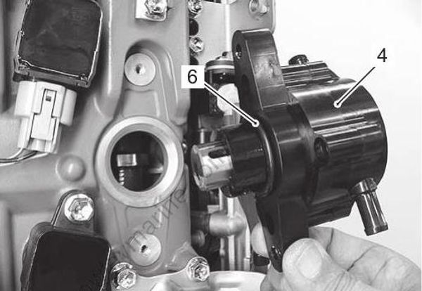
- Remove the low pressure fuel pump (4).
Note the position before removing O-ring (6).
Installation
Installation is in the reverse order of removal with special attention to the following steps.
• Before installing the low pressure fuel pump, rotate the crankshaft to bring the No.1 (top cylinder) piston to Top Dead Center on the compression stroke.
• Do not reuse O-ring once removed. Always use a new O-ring.
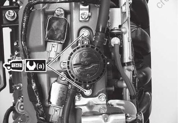
- Apply thread lock to the low pressure fuel pump bolts.
Thread lock cement 99000–32050 (SUZUKI Thread Lock 1342 (50 g))
- Install the low pressure fuel pump, then tighten bolts securely.
Tightening torque
Low pressure fuel pump bolt (a): 10 N•m (1.0 kgf•m, 7.0 lbf•ft)
- Connect the fuel inlet and outlet hoses.
- Reinstall parts removed earlier.
Low Pressure Fuel Pump Inspection
Disassembling the low pressure fuel pump can lead to troubles. The low pressure fuel pump is a non-repairable component. Do not attempt to disassemble the low pressure fuel pump. It must be replaced as a complete unit if it is defective.
Low Pressure Fuel Pump
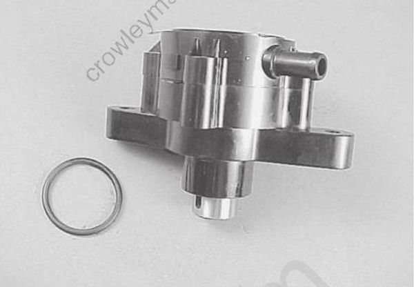
Inspect the low pressure fuel pump.
If leakage, cracks, damage or other abnormal condition is found, replace fuel pump assembly.
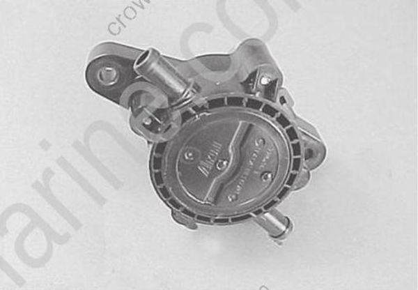
Low Pressure Fuel Line Components
When disassembling or reassembling fuel line, refer to the construction diagram below.
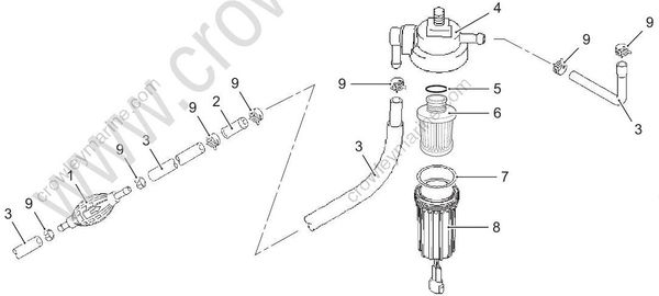
- Primer bulb
- Fuel connector
- Fuel hose
- Low pressure fuel filter body
- Seal ring
- Filter element
- O-ring
- Low pressure fuel filter cup/water detection switch
- Clip
Low Pressure Fuel Filter / Fuel Hose Inspection
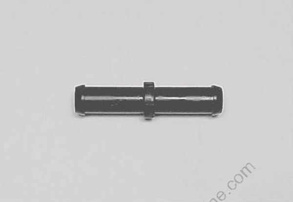
Fuel Connector
Inspect fuel connector for leakage, deterioration or other damage. Replace if necessary.
Fuel Hose
Inspect fuel hose for cuts, cracks, leakage, tears or deterioration. Replace if necessary.
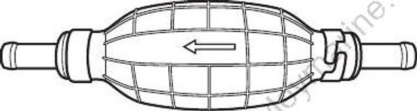
Fuel Primer Bulb
Inspect fuel primer bulb for cracks, leakage, deterioration or check valve function. Replace if necessary.
Low Pressure Fuel Filter
Inspect low pressure fuel filter (1).
Refer to“Low Pressure Fuel Filter Inspection” in Section 0B (Page 0B-17).
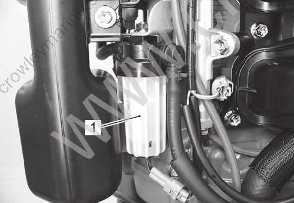
High Pressure Fuel Filter Removal and Installation
Removal
Gasoline is a flammable material that can cause fire hazard or burns. Before starting the following procedure, be sure to observe “Precautions on Fuel System Service” (Page 1G-1) in order to reduce the risk or fire and personal injury.
Relieve the fuel pressure in the fuel feed line.
Refer to “Fuel Pressure Relief Procedure” (Page 1G 16).Loosen the three bolts and remove the fuel hose guard (1).
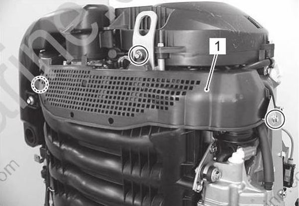
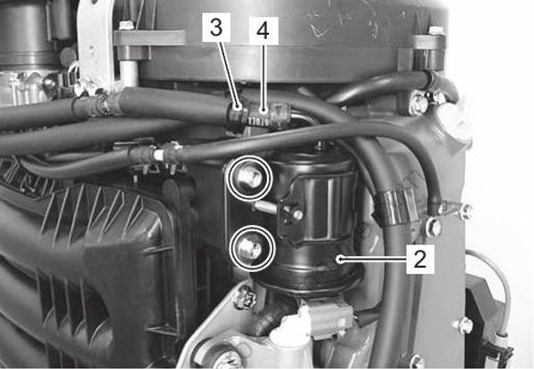
Remove the two bolts securing high pressure fuel filter (2).
Remove the hose clip (3).
Loosen the clamp and place a large cloth over end of fuel feed hose (4).
Slowly pull fuel feed hose (4) from high pressure fuel filter.
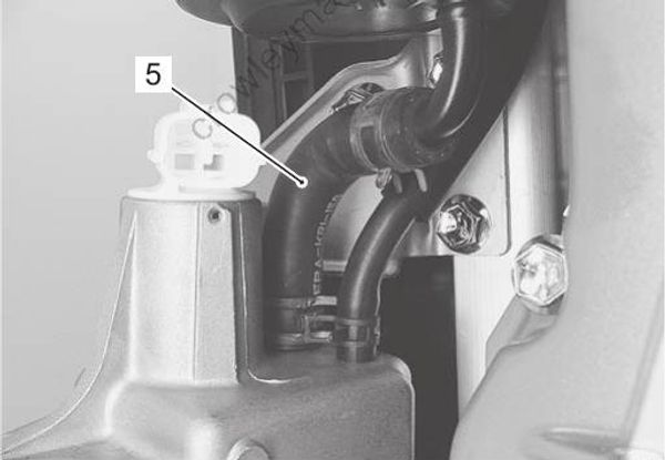
- Loosen the clamp and place a large cloth over end of fuel hose (5), then disconnect fuel hose (5) from high pressure fuel filter.
Drain any excess fuel in filter into a small container.
Installation
Installation is reverse order of removal with special attention to the following steps.
Check fuel hose routing.
Refer to “Fuel Hose Routing” in Section 4B (Page 4B 1).Check for fuel leakage.
Refer to “Fuel Leakage Check Procedure” (Page 1G 17).
Water Detection Switch Inspection
Inspect the water detection switch using the following procedures.
Remove the low pressure fuel filter.
Remove filter cup.
Refer to “Low Pressure Fuel Filter Inspection” in Section 0B (Page 0B-17).Connect the tester probes to the lead wire terminals as shown.
Check if continuity/infinity can be measured by moving float, checking each position.
If out of specification, replace the switch (fuel filter case) with a new one.
Special tool
(A): 09900–25008 (Multi circuit tester set)
Tester knob indication
Continuity( )
| Float position | Tester indication |
|---|---|
| Raise the float fully up | Continuity |
| Lower the float completely | Infinity |
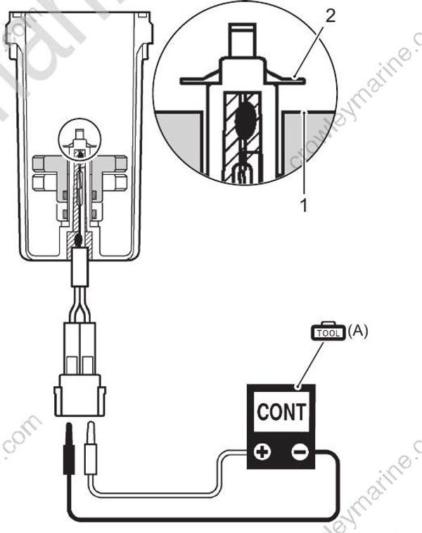
- Float
- Stopper
- Assemble and re-install the fuel filter.
Refer to “Low Pressure Fuel Filter Inspection” in Section 0B (Page 0B-17).
