Engine Control
Precautions
Precautions on Engine Control Diagnosis
Service operation of any type performed on engine control system involves a risk of fire and personal injury if proper precaution are not taken. To prevent any unexpected engine starting, perform the following before proceeding with any CRANKING tests.
• When performing tests not related to fuel injector operation: – Disconnect all fuel injector wire connectors.
• When performing tests related to fuel injector operation:
– Relieve the fuel pressure in the fuel lines. Refer to “Fuel Pressure Relief Procedure” in Section 1G (Page 1G-16).
– Disconnect the high pressure fuel pump wire connector located on the fuel vapor separator.
If you do not disconnect the battery before disconnecting or connecting the wiring harness, you could get an electrical shock. Always turn the main switch “OFF” and disconnect the battery cables when wires are being disconnected or connected.
Failure to take proper precaution when disconnecting the harness connector can cause damage to the wiring harness. Hold and pull the connectors when disconnecting. Do not pull the wires.
• To troubleshoot the ECM, BCM and the engine control system, consisting of sensors and actuators, use the Suzuki Diagnostic System.
• When ECM or BCM has been replaced, it is necessary to perform the initialization and re-calibration of SPC system.
• The self-diagnostic codes memory in the ECM will remain even if the battery is disconnected.
• Each electrical circuit is affected by battery voltage, always use a full-charged battery.
• Make sure all ground points have good electrical contact.
• Make sure all wires/cables are securely connected.
General Description
Engine Control System Description
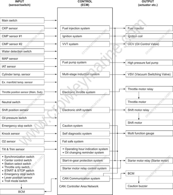
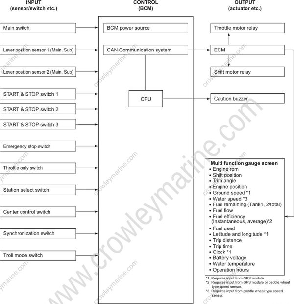
The DF200AP models employ an integrated control system which performs the control functions for electronic gear shift system, electronic throttle system, fuel injection, ignition, etc. through the BCM (Boat Control Module) and ECM (Engine Control Module).
System Structure
Control Module for System Control
Engine Control Module (ECM)
The ECM sends signals to control the actuators based on the information inputs from each sensor/switch and BCM (Boat Control Module). Major controls are as follows:
| Name of control | Description |
|---|---|
| Fuel injection control | •Controls fuel injection amount and timing. |
| Ignition control | •Controls ignition timing. |
| Electronic throttle system | •Controls engine speed by adjusting intake air amount through electronic throttle system. |
| VVT system | •Controls intake cam valve timing through OCV (Oil Control Valve). |
| Fuel pump control | •Controls high pressure fuel pump drive. |
| Multi-stage induction system | •Changing the length of intake manifold pipes according to engine speed. |
| Caution system control | • Informs operator of abnormal engine condition. •Controls engine speed, if activated. |
| Self-diagnostic system control | •Informs operator of sensor/switch malfunction. |
| Fail-safe system control | •Allows engine operation with a back-up system during sensor/switch malfunction. |
| Total operating hour indication system control | •Informs operator of total operating time. |
| Oil changing reminder system control | •Informs operator of time for replacing engine oil on the basis of the maintenance schedule. |
| Start-in-gear protection system control | •Prevents engine start when shift is positioned in forward or reverse. |
| Starter motor relay control system | •Prevents starter motor operation when engine is already operating. |
| Electronic gear shift system | •Controls gear shifting by controlling shift actuator. |
| CAN communication system | •ECM and BCM communicate control data between each module.Communication is established by CAN (Controller Area Network) communication system. |
| Power trim and tilt relay control system | •Controls On/Off for the PTT relay’s up and down circuits. |
| Water in fuel alert system | •Informs operator of water accumulates in the low pressure fuel filter. |
Information related to the caution system, self-diagnostic system and total operating hour indication system is retained in ECM memory.
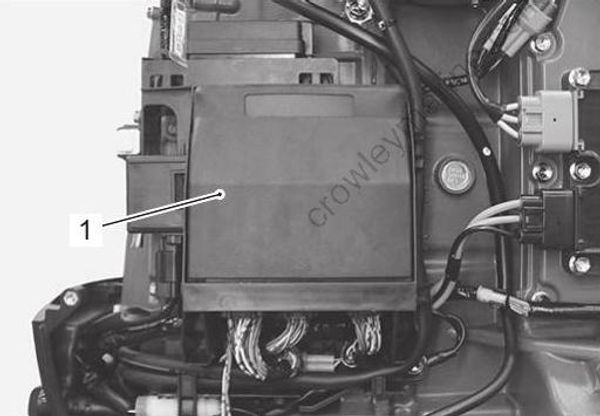
- ECM
Boat Control Module (BCM)
BCM sends a signal value (control signal) to ECM on the basis of input signals from switches and sensors. Based on the received signal value from BCM, ECM controls the engine and the actuators.
BCM controls the caution buzzer with the current engine condition detected through ECM. The major controls are as follows:
| Name of control | Description |
|---|---|
| Throttle control | • In accordance with the control lever position (input signal from LPS) of the respective engines, the throttle operation is controlled for each engine independently. • By operating the throttle only switch, the throttle open or close operation is controlled with the shift position held in neutral. |
| Shift control | • In accordance with the control lever position of the respective engines, the shift operation is controlled for each engine independently. |
| Center control | • In the case of triple engines, the interlink between the CENTER and PORT engines is released with the center control switch operated.At this time, the CENTER engine is set to idle throttle opening (neutral position). |
| Start & stop control | • During the engine at stop, pressing START & STOP switch once controls the auto-start of the engine. • During engine in operation, pressing START & STOP switch continuously for a given duration stops the engine. |
| Synchronization | • In the case of multi engines, pressing the synchronization switch automatically adjusts the speed of each engine to that of PORT engine approximately. • By operating the synchronization switch, either turning on or off the synchronization function can be selected. |
| Caution buzzer control | • The caution buzzer at each operator seat are controlled according to engine operating conditions. |
| LED control | • The lighting of LED in the switch panel at each operator seat is controlled according to the boat and engine operating conditions. |
| Engine stop control | • The engine stopping is controlled by the signal sent from the emergency stop switch. |
• After completion of rigging, the following calibration must be made to the BCM using SDS Ver.8 and PC prior to boating.
– Number of stations – Number of engines
– Position of outboard motor
– Characteristic of remote control lever
– Full trim down position
• One BCM should be installed for each station.
• In the case of two stations, BCM of the 1st station is the master BCM and that of the 2nd station is the sub-BCM.
• The sub-BCM functions as an input/output device for the master BCM.
• In the case of triple engines, normally the CENTER engine interlinks with the PORT engine. The CENTER engine is controlled with the PORT remote control lever.
• Pressing START & STOP switch once closes (ON) the starter circuit for three seconds but when the engine has been started, the circuit opens (OFF).
• Synchronization control will not function when PORT and STBD remote control lever positions are different from each other.
In the case of quadruple engine installation:
• Two BCM are required for single station.
– One BCM for the port and port center engines (port engine group).
– The other BCM for the starboard and starboard center engines (starboard engine group). Also four BCMs are required for dual station.
• While communicating the BCM each other, the BCM controls to prevent mismatches between two engine groups that are the port and port center engines and the starboard and starboard center engines.
• Engine is controlled by SPC twin lever remote control box.
– The port remote control lever controls both port engine and port center engine.
– The starboard remote control lever controls both starboard engine and starboard center engine.
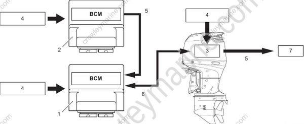
- Master BCM (1st station)
- Sub BCM (2nd station
- ECM
- Sensor/switch signal
- Control signal
- CAN communication
- Engine/actuator
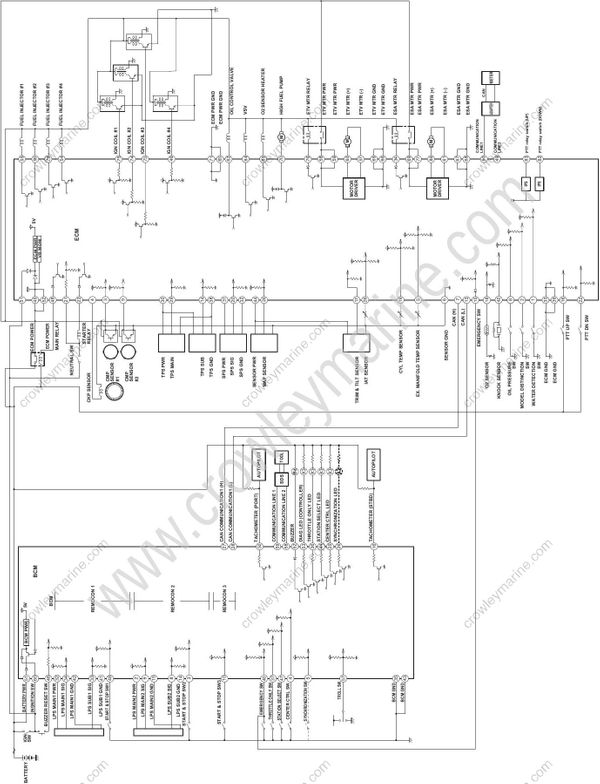
ECM and BCM Input / Output Circuit Diagram (Normal Key Start Model)
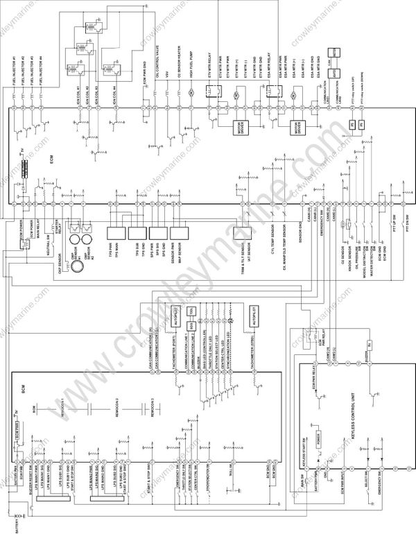
ECM and BCM Input / Output Circuit Diagram (Keyless Start Model)
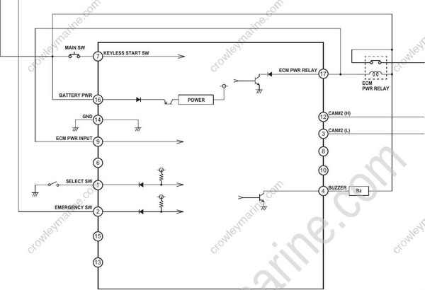
Keyless Control Unit Input / Output Circuit Diagram
ECM Connector / Terminals Layout
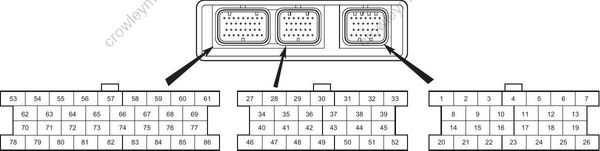
| Terminal | Wire color | Circuit | Terminal | Wire color | Circuit |
|---|---|---|---|---|---|
| 1 | R/Bl | Water detection switch | 44 | R | Power source for sensors |
| 2 | O/Y | Model distinction switch | 45 | Gr | Power source for ECM |
| 3 | Y/Bl | CMP sensor 1 | 46 | Lg/R | No.4 Ignition coil |
| 4 | R/B | CKP sensor | 47 | ― | ― |
| 5 | V/W | EX manifold temp. sensor | 48 | O | ECM main relay |
| 6 | B/W | Ground for sensors | 49 | Y | Communication line No.2 |
| 7 | W | CAN 1 (H) | 50 | O/Y | Communication line No.1 |
| 8 | Bl | Oil pressure switch | 51 | Y/G | Ignition switch |
| 9 | O/G | CMP sensor 2 (VVT) | 52 | Gr | Power source for ECM |
| 10 | ― | ― | 53 | ― | ― |
| 11 | ― | ― | 54 | Lg | No.4 Fuel injector |
| 12 | ― | ― | 55 | O/B | No.1 Fuel injector |
| 13 | B | CAN 1 (L) | 56 | B/Br | No.2 Fuel injector |
| 14 | P/W | Throttle position sensor (Sub) | 57 | W/Bl | Throttle motor (-) |
| 15 | Bl/R | Emergency stop switch | 58 | Y | Power source for Throttle motor |
| 16 | Lbl | PTT switch (UP) | 59 | Y | Power source for Throttle motor |
| 17 | W/Y | Trim and tilt sensor | 60 | R/Y | Throttle motor (+) |
| 18 | Gr/Bl | O2 sensor | 61 | G | Shift motor (-) |
| 19 | Lg/W | Cylinder temp. sensor | 62 | Br/W | OCV |
| 20 | P/Bl | Shift position sensor | 63 | B | Ground for ECM power |
| 21 | Br | Neutral switch | 64 | ― | ― |
| 22 | P | PTT switch (DOWN) | 65 | B | Ground for Throttle motor |
| 23 | G/B | Starter relay control | 66 | B | Ground for Throttle motor |
| 24 | W | MAP sensor | 67 | B | Ground for Shift motor |
| 25 | ― | ― | 68 | B | Ground for Shift motor |
| 26 | Lg/B | IAT sensor | 69 | Gr/R | Power source for Shift motor |
| 27 | ― | ― | 70 | B/R | High pressure fuel pump |
| 28 | ― | ― | 71 | B | Ground for ECM power |
| 29 | Br/Y | Throttle position sensor (Main) | 72 | ― | ― |
| 30 | R/Bl | Power source for TPS | 73 | Gr/Y | No.3 Ignition coil |
| 31 | R/W | Power source for SPS | 74 | Bl | No.2 Ignition coil |
| 32 | Br/B | Ground for SPS | 75 | O | No.1 Ignition coil |
| 33 | B | Ground for ECM | 76 | W/B | Throttle motor relay |
| 34 | G/Bl | Shift motor relay | 77 | Gr/R | Power source for Shift motor |
| 35 | ― | ― | 78 | ― | ― |
| 36 | ― | ― | 79 | R/W | No.3 Fuel injector |
| 37 | W/G | CAN 2 (H) | 80 | ― | ― |
| 38 | B/W | Ground for TPS | 81 | ― | ― |
| 39 | B | Ground for ECM | 82 | P | PTT relay (DOWN) |
| 40 | ― | ― | 83 | Lbl | PTT relay (UP) |
| 41 | ― | ― | 84 | O/W | VSV |
| 42 | P/Y | Knock sensor | 85 | Lg/Bl | O2 sensor heater |
| 43 | B/Lg | CAN 2 (L) | 86 | R | Shift motor (+) |
BCM Connector / Terminal Layout For single / twin / triple engine

| Terminal | Wire color | Circuit | Terminal | Wire color | Circuit |
|---|---|---|---|---|---|
| 1 | — | — | 31 | — | — |
| 2 | R/Y | Power source for lever position sensor main 2 | 32 | R/W | Power source for lever position sensor main 1 |
| 3 | Y/B | Start & Stop switch 2 | 33 | W/B | Lever position sensor sub 1 |
| 4 | Lg/B | Center control switch | 34 | Bl/W | Lever position sensor main 1 |
| 5 | O/B | Synchronization switch | 35 | B | Ground for BCM |
| 6 | — | — | 36 | G | Throttle only LED |
| 7 | — | — | 37 | G/B | Throttle only switch |
| 8 | Bl/Y | Lever position sensor sub 2 | 38 | — | — |
| 9 | W/Y | Lever position sensor main 2 | 39 | — | — |
| 10 | Y/R | Start & Stop switch 3 | 40 | G | Emergency stop switch |
| 11 | — | — | 41 | — | — |
| 12 | — | — | 42 | B/W | Lever position sensor 1 GND |
| 13 | — | — | 43 | B | Ground for BCM |
| 14 | — | — | 44 | Br | Station select LED |
| 15 | B/Y | Lever position sensor 2 GND | 45 | — | — |
| 16 | Y | Tachometer (STBD) | 46 | O | Buzzer reset switch |
| 17 | — | — | 47 | Br/W | Station select switch |
| 18 | — | — | 48 | Y/G | Start & Stop switch 1 |
| 19 | — | — | 49 | — | — |
| 20 | — | — | 50 | Y/B | Tachometer (PORT) |
| 21 | — | — | 51 | W | BCM power source |
| 22 | — | — | 52 | Bl | Buzzer |
| 23 | — | — | 53 | G/W | Diag LED |
| 24 | — | — | 54 | — | — |
| 25 | Lg | Center engine control LED | 55 | — | — |
| 26 | O | Synchronization LED | 56 | — | — |
| 27 | W | CAN 1 (H) | 57 | Lg/G | Troll mode switch |
| 28 | B | CAN 1 (L) | 58 | Y | Communication line No.2 |
| 29 | — | — | 59 | O/Y | Communication line No.1 |
| 30 | — | — | 60 | Gr | Main switch |
For quadruple engine (STBD engine group)

| Terminal | Wire color | Circuit | Terminal | Wire color | Circuit |
|---|---|---|---|---|---|
| 1 | — | — | 31 | — | — |
| 2 | R/Y | Power source for LPS main 2 | 32 | — | — |
| 3 | Y/Bl | Start & Stop switch 2 | 33 | Bl/Y | Lever position sensor sub 1 |
| 4 | Lg/B | Center control switch | 34 | W/Y | Lever position sensor main 1 |
| 5 | O/B | Synchronization switch | 35 | B/Bl | Ground for BCM |
| 6 | — | — | 36 | G/Y | Throttle only LED |
| 7 | — | — | 37 | G/B | Throttle only switch |
| 8 | Bl/Y | Lever position sensor sub 2 | 38 | — | — |
| 9 | W/Y | Lever position sensor main 2 | 39 | — | — |
| 10 | Y/R | Start & Stop switch 3 | 40 | G | Emergency stop switch |
| 11 | — | — | 41 | — | — |
| 12 | — | — | 42 | B/Y | Lever position sensor 1 GND |
| 13 | — | — | 43 | B/Bl | Ground for BCM |
| 14 | — | — | 44 | Br | Station select LED |
| 15 | B/Y | Lever position sensor 2 GND | 45 | — | — |
| 16 | Y | Tachometer (STBD) | 46 | O | Buzzer reset switch |
| 17 | O/G | Hi-Lo Output | 47 | Br/W | Station select switch |
| 18 | — | — | 48 | Y/G | Start & Stop switch 1 |
| 19 | — | — | 49 | — | — |
| 20 | — | — | 50 | Y/B | Tachometer (PORT) |
| 21 | G/R | Hi-Lo Input | 51 | W | BCM power source |
| 22 | — | — | 52 | Bl | Buzzer |
| 23 | — | — | 53 | G/W | Diag LED |
| 24 | — | — | 54 | — | — |
| 25 | Lg | Center engine control LED | 55 | — | — |
| 26 | O/Bl | Synchronization LED | 56 | — | — |
| 27 | W/B | CAN 1 (H) | 57 | Lg/G | Troll mode switch |
| 28 | B/W | CAN 1 (L) | 58 | Y/W | Communication line No.2 |
| 29 | — | — | 59 | O/Y | Communication line No.1 |
| 30 | — | — | 60 | Gr | Main switch |
For quadruple engine (PORT engine group)

| Terminal | Wire color | Circuit | Terminal | Wire color | Circuit |
|---|---|---|---|---|---|
| 1 | — | — | 31 | — | — |
| 2 | — | — | 32 | R/W | Power source for LPS main 1 |
| 3 | Y/B | Start & Stop switch 2 | 33 | W/Bl | Lever position sensor sub 1 |
| 4 | Lg/B | Center control switch | 34 | Bl/W | Lever position sensor main 1 |
| 5 | O/B | Synchronization switch | 35 | B | Ground for BCM |
| 6 | — | — | 36 | G/Y | Throttle only LED |
| 7 | — | — | 37 | G/B | Throttle only switch |
| 8 | W/Bl | Lever position sensor sub 2 | 38 | — | — |
| 9 | Bl/W | Lever position sensor main 2 | 39 | — | — |
| 10 | Y/R | Start & Stop switch 3 | 40 | G | Emergency stop switch |
| 11 | — | — | 41 | — | — |
| 12 | — | — | 42 | B/W | Lever position sensor 1 GND |
| 13 | — | — | 43 | B | Ground for BCM |
| 14 | — | — | 44 | Br | Station select LED |
| 15 | B/W | Lever position sensor 2 GND | 45 | — | — |
| 16 | Y/W | Tachometer (STBD) | 46 | O | Buzzer reset switch |
| 17 | G/R | Hi-Lo Output | 47 | Br/W | Station select switch |
| 18 | — | — | 48 | Y/G | Start & Stop switch 1 |
| 19 | — | — | 49 | — | — |
| 20 | — | — | 50 | Y/R | Tachometer (PORT) |
| 21 | O/G | Hi-Lo Input | 51 | W/B | BCM power source |
| 22 | — | — | 52 | Bl | Buzzer |
| 23 | — | — | 53 | G/W | Diag LED |
| 24 | — | — | 54 | — | — |
| 25 | Lg | Center engine control LED | 55 | — | — |
| 26 | O/Bl | Synchronization LED | 56 | — | — |
| 27 | W | CAN 1 (H) | 57 | Lg/G | Troll mode switch |
| 28 | B/R | CAN 1 (L) | 58 | Y | Communication line No.2 |
| 29 | — | — | 59 | O/Y | Communication line No.1 |
| 30 | — | — | 60 | Gr/R | Main switch |
| Keyless Control Unit Connector / Terminal Layout |

| Terminal | Wire color | Circuit | Terminal | Wire color | Circuit |
|---|---|---|---|---|---|
| 1 | Y | Select switch | 10 | — | — |
| 2 | G | Mode switch (Emergency stop switch) | 11 | — | — |
| 3 | B/Lg | CAN (L) | 12 | W/G | CAN (H) |
| 4 | Bl | Buzzer | 13 | — | — |
| 5 | ― | ― | 14 | B | GND |
| 6 | ― | ― | 15 | — | — |
| 7 | Gr | Ignition switch | 16 | W | Battery power |
| 8 | ― | ― | 17 | P/B | ECM power relay |
| 9 | P/B | ECM power input | 18 | — | — |
Electronic Shift System Description
Outline
The electronic shift system consists of lever position sensor assembly, ECM, BCM, shift control actuator relay and shift actuator.
Operation
ECM detects the remote control lever position by the voltage signal sent from the lever position sensor which is built in the remote control box.
ECM receives the lever position sensor signal through BCM and drives the actuator motor so that the actual clutch lever (gear) position agrees with the detected target shift position (lever position voltage signal). Thus, gear shifting to forward, neutral or reverse is performed.
The actual shift position is checked by the shift position sensor detecting it and is feed back to ECM.When a failure is detected in the system components, the shift motor relay is turned off causing the shift actuator drive to be interrupted.
When the remote control box is replaced, the setting change should be performed using SDS Ver. 8.
When ECM is replaced, BCM initialization and the system calibration should be performed using SDS Ver. 8.
• The shift change can be done by remote control lever only when ECM receives signal of engine turning. The shift change can not be done by remote control lever during engine stopping even main switch is ON position.
• When engine is stopped, ECM controls the shift actuator to shift in neutral regardless the position of remote control lever.
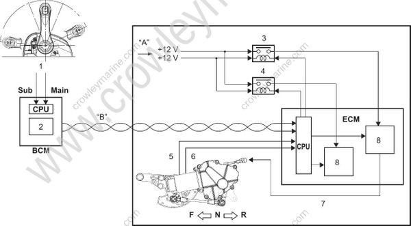
- LPS signal (main and sub)
- CAN driver
- ESA motor relay
- ETV motor relay
- Shift position sensor signal
- Neutral switch signal
- ESA motor operating signal|
- Motor driver
“A”:From main relay|
“B”:CAN communication|
Switch Panel Description
BCM performs the engine control according to the signal from various switches as explained below:
In the case of quadruple engine installation: Use two control panels for dual engine installation. When operating the SELECT, THROTTLE ONLY and SYNC function, all four engines are controlled by either control panel switch.
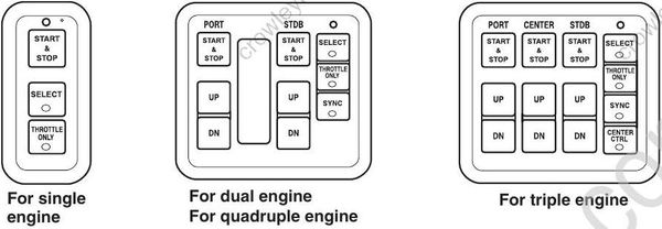
Start & Stop Switch
BCM performs control of engine starting and stopping by a signal from START & STOP switch on the basis of engine speed.
START & STOP switch

Start control
BCM generates the start signal for each engine based on START & STOP switch signal in accordance with the current engine condition.
Pressing START & STOP switch once cranks the engine for three seconds continuously for starting.
Holding START & STOP switch pressed cranks the engine continuously until the engine starts. When the engine speed exceeds the predetermined level, the start signal will be reset.The continuous operating time of the starter motor is set at five seconds. When this time is exceeded, the starter motor will automatically stop.
If the motor stops, wait about ten seconds for the motor to cool down and try again.Unless the actual shift position is in neutral, the start signal will not be generated.
When the shift position sensor fails, Neutral is indicated in the meter LCD display regardless of whether the position is F, N or R.
Stop control
BCM generates the stop signal on the basis of START & STOP switch signal.
Pressing START & STOP switch once during operation will set the stop signal and perform the engine stop control.
When the engine stop has been confirmed, the stop signal will be reset.When the engine stops, the caution buzzer sounds twice briefly.
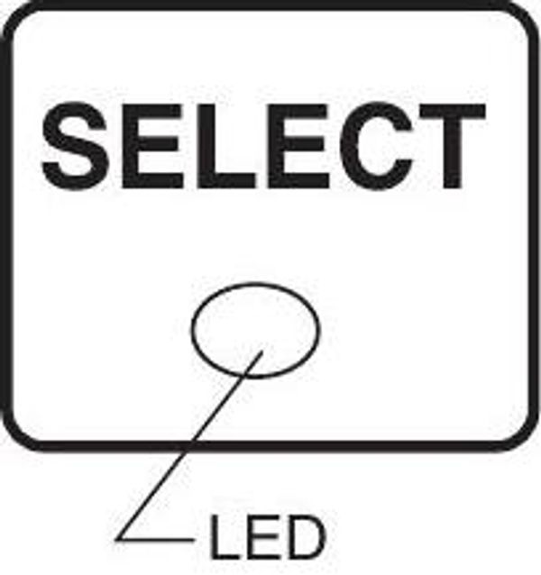
Select Switch
This switch selects the 1st or 2nd station in the case of a 2-station system.
By operating the remote control lever and switch in the selected station, BCM control is performed.When the main switch is turned from OFF to ON, the 1st station will be selected.
Only when all stations remote control levers are in the neutral position, the station selection can be made. If the switch operation is made in other than neutral position, the select switch LED starts to flash and the caution buzzer will sound briefly.
In the selected station, the select switch LED will turn on and in the unselected station, the LED will go off.
The remote control lever and switch in the unselected station will be inoperative due to BCM control except the main switch and emergency stop switch that remain constantly operational.
The output operation of LED and buzzer in the unselected station are the same as those in the selected station except the select switch LED.
SELECT switch
Throttle Only Switch
Regardless of remote control lever operation,
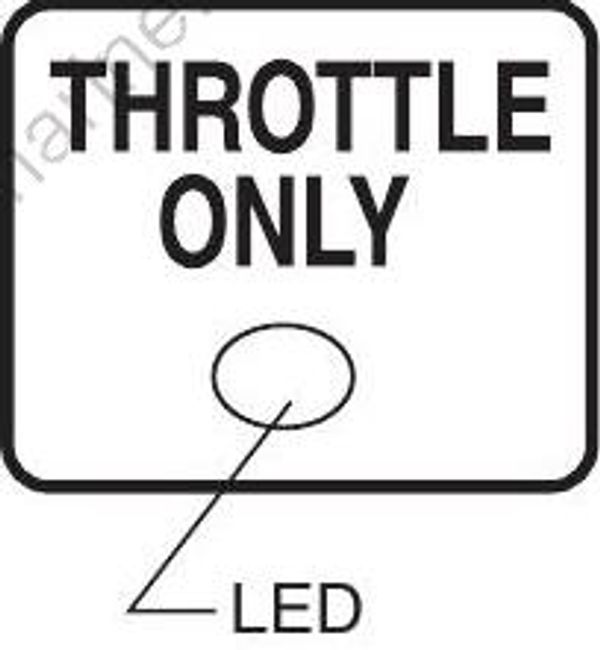
THROTTLE ONLY switch fixes the shift position into neutral. (Free throttle mode)In the free throttle mode, THROTTLE ONLY switch LED turns on.
Only when the remote control lever is in neutral, ON signal of THROTTLE ONLY switch is receivable to activate free throttle mode.
If the switch is operated other than in neutral, THROTTLE ONLY switch LED flashes and the caution buzzer starts to sound briefly.To cancel the free throttle mode, shift the remote control lever to neutral and press THROTTLE ONLY switch once again.
THROTTLE ONLY switch
Synchronization Switch
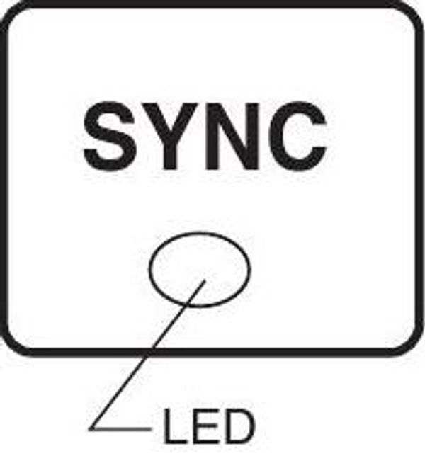
In the case of multi engines, BCM monitors the actual speed of each engine and controls the target throttle opening of other than PORT engines to synchronize with PORT engine speed.
To implement the synchronization control, select the synchronization mode by pressing SYNC switch.
This control should be made during forward running. The control will become inactive during acceleration, deceleration, no load condition, idle/trolling speed and WOT running.
When the synchronization mode is active, SYNC switch LED turns on.During synchronization control in process, if the engine operating condition is changed by operating the remote control lever, the synchronization control will be canceled.
When PORT and STBD remote control levers are in different position from each other, the synchronization control will be inoperative.
In the case of quadruple engine installation:
• Engine speed is synchronized with port side engine speed on each (STBD/PORT) engine group. However, two engine groups never be synchronized each other.
SYNC switch
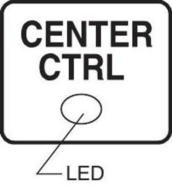
Control: Center Control Switch
In the case of triple engines, CENTER CTRL switch selects either interlinking or unlinking of the center engine with PORT engine.
The switch operating signal is active only when all the remote control levers are in neutral.
During interlinking state, pressing the switch once will change it to unlinking state. Pressing the switch once again during unlinking state will change it to interlinking state.
If the switch is pressed in other than neutral position, CENTER CTRL switch LED flashes and the caution buzzer starts to sound.During center engine control mode in process, the center engine interlinks with PORT engine. During other than center control modes, the engines are unlinked and the idle opening (Neutral) takes place.
When the main switch is turned from OFF to ON, the center control mode takes place.
During center control mode, CENTER CTRL switch LED turns on.
CENTER CTRL switch
PTT Switch
The “Power Trim and Tilt” is operated by pressing the switch.
To tilt up, press the UP switch. To tilt down, press the DN switch.
The tilt up and tilt down switches can not be activated when the main switch is off.
PTT switch

Caution System Description
The following caution systems alert the operator when an abnormality occurs on the engine.
When a problem is detected, the caution name appears on the display screen of multi function gauge, caution buzzer sounds continuously.
- OVER-REVOLUTION CAUTION
- LOW OIL PRESSURE CAUTION
- OVERHEAT CAUTION
- LOW BATTERY VOLTAGE CAUTION
- CONTROL UNIT COMMUNICATION CAUTION
- SECOND STATION CAUTION
- THROTTLE SYSTEM CAUTION
- SHIFT CONTROL CAUTION
- GAUGE COMMUNICATION
- KEY FOB CAUTION *1
- KEY FOB LOW BATTERY VOLTAGE CAUTION *1
- KEYLESS CONTROL UNIT LOW BATTERY VOLTAGE CAUTION *1
(*1: Keyless start model only)
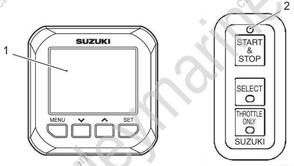
- Multi function gauge
- BCM (Red) Lamp
| Caution type | Gauge display indication | Caution buzzer | Over-rev limiter | BCM (Red) lamp |
|---|---|---|---|---|
| Over-revolution | Over Revolution | Yes | Yes (3 000 r/min) | — |
| Low oil pressure | Low Oil Pressure | Yes | Yes (1 000 r/min) | — |
| Overheat | Overheat | Yes | Yes (3 000 r/min) | — |
| Low battery voltage | Low Battery Voltage | Yes | No | — |
| Control unit communication | Check Control Unit C. | Yes | No | ON |
| Second station | Check 2nd Station | Yes | No | ON |
| Throttle system | Check Throttle System | Yes | No | — |
| Shift control | Check Shift Control | Yes | No | — |
| Gauge communication | Check Gauge C. | No | No | — |
| Key-fob *1 | Check Remote Key | No | No | — |
| Key-fob low battery voltage *1 | Remote Key Battery Low | No | No | — |
| Keyless control unit low battery voltage *1 | Keyless Unit Battery Low | No | No | — |
(*1: Keyless start model only)
Buzzer Check
When the main key is turned to ON position, caution buzzer sounds for three seconds.
Over-Revolution Caution System Condition:
The ECM controlled over revolution limiter will engage at the engine speeds shown below. Once engaged it will initiate an intermittent fuel injection signal to reduce engine speed.
Over revolution limiter
DF200AP: 6 300 r/min.
Action:
When the engine speed detected by ECM exceeds the preset maximum engine speed, the gauge display screen will indicate “Rev Limit”.
If this condition continues for ten seconds, the engine speed will be limited to approximately 3 000 r/min by making the fuel injection signal intermittent.
At the same time, the gauge display screen indicates “Over Revolution” and the caution buzzer turns on.If the engine speed is reduced to the over revolution system maximum preset value or lower within ten seconds, the over revolution caution will be automatically canceled.
By pressing any of gauge button, the “Over Revolution” indication will be cleared.
Reset:
Close throttle to reduce engine speed below approx. 3 000 r/min for one second.
Low Oil Pressure Caution System
Condition:
Immediate activation of system when the oil pressure switch is turned “ON” due to an engine oil pressure drop below 100 kPa (1.0 kg/cm2, 14 psi).
Action:
When this system operates, the gauge screen will indicate “Low Oil Pressure” and caution alarm icon. At the same time, the caution buzzer sounds.
If this caution system operates at higher than 1 000 r/ min, the engine speed will be reduced to approximately 1 000 r/min by making the fuel injection signal intermittent.
The engine automatically stops 3 minutes after the caution system is activated.
By pressing any of gauge button, the “Low Oil Pressure” indication will be cleared. However, the caution alarm icon is displayed until the cause is eliminated.
If the engine is automatically stopped due to the caution system, the engine can be started again. However, the caution system will repeatedly activate until the cause is eliminated.
Reset:
Stop engine and check engine oil level. Refill engine oil to the correct level if below the low oil mark.
If the engine oil level is correct, the following causes may be considered:
- Improper oil viscosity.
- Malfunctioning oil pressure switch.
- Clogged oil strainer or oil filter.
- Worn oil pump relief valve.
- Oil leakage from the oil passage.
- Excessive wear/damage of oil pump.
The low oil pressure caution system is reset when the oil pressure is restored to over 1.0 kg/cm2 with approx. 1 000 r/min or less engine speed operation. However, the engine must be stopped and checked immediately once the system is activated.
Overheat Caution System
Condition 1 (Maximum temperature)
Immediate activation of system when:
- Cylinder temperature reaches 110 °C (230 °F)
- Exhaust manifold temperature reaches 104 °C (219 °F)
Condition 2 (Temp. rise vs Time)
Immediate activation of system when:
- The average temperature difference during three consecutive 8 second measurement periods of the cylinder temperature sensor at engine speeds of 500 r/min or higher exceeds the limits as shown below.
| Temperature range | Temperature difference |
|---|---|
| 80 – 89 °C(176 – 192 °F) | Approx. 6 °C (10 °F) |
| 90 °C – (194 °F –) | Approx. 1 °C (1.8 °F) |
- The average temperature difference during three consecutive 8 second measurement periods of the exhaust manifold temperature sensor at engine speeds of 500 r/min or higher exceeds the limits as shown below.
| Temperature range | Temperature difference |
|---|---|
| 72 – 84 °C(161 – 183 °F) | Approx. 11 °C (20 °F) |
| 85 °C – (185 °F –) | Approx. 1 °C (1.8 °F) |
Action:
When this system operates, the gauge screen will indicate “Overheat” and caution alarm icon. At the same time, the caution buzzer sounds.
If this caution system operates at higher than 3 000 r/min, the engine speed will be reduced to approximately 3 000 r/min by making both the fuel injection and ignition signals intermittent.
The engine automatically stops 3 minutes after the caution system is activated.
By pressing any of gauge button, the “Overheat” indication will be cleared. However the caution alarm icon is displayed until the cause is eliminated.
If the engine is automatically stopped due to the caution system, the engine can be started again. However, the caution system will repeatedly activate until the cause is eliminated.
Reset:
Close throttle completely and then shift into neutral.
System reset will occur when cylinder temperature drops below the limits shown below. However, the system may be activated again unless the cause for overheat (such as insufficient water) is removed.
| Caution cause | Reset temperature |
|---|---|
| Condition 1(Maximum temperature) | Approx. 70 – 78 °C (158 – 172 °F) |
| Condition 2(Temperature rise vs Time) | Approx. 68 – 76 °C (154 – 169 °F) |
Low Battery Voltage Caution System
Condition 1:
System is activated when the battery voltage decreases to less than 9 V for 30 seconds.
Condition 2:
System is activated if the battery voltage is less than 2 V for more than 2 seconds with the main switch is turned “ON” and the engine not running.
Action:
When this system operates, the gauge screen will indicate “Low Battery Voltage” and caution alarm icon. At the same time, the caution buzzer sounds.
By pressing any of gauge button, the “Low Battery Voltage” indication will be cleared. However, the caution alarm icon is displayed until the cause is eliminated.
Reset:
Condition 1:
This caution system is automatically reset when battery voltage increases to more than 9 V. Refrain from using electrical equipment requiring high amperage such as hydraulic trim tabs, hydraulic jack plate, etc. after this caution is activated.
Condition 2:
For the caution system to engage under this condition possibilities such as a deteriorated battery, poor battery cable connection, battery switch in the OFF position, etc, must be inspected.
To cancel the caution system activation for these conditions, check all power source related items and eliminate the problem.
Control Unit Communication Caution System
Condition:
This system operates when a failure has occurred in the control of electrical shift system or electrical throttle system including electrical remote control box.
Action:
When the system operates, the gauge screen will indicate “Check Control Unit C.” and caution alarm icon. At the same time, the caution buzzer sounds.
In addition, a red light on the control panel turns on. By pressing any of gauge button, the “Check Control Unit C.” indication will be cleared.
However, the caution alarm icon is displayed until the cause is eliminated.
Detail of the caution can be checked by selecting diagnosis menu on multi function gauge. Diagnosis code “7-5” will appear on the gauge screen.
When the system operates, the engine will keep running at idle (in neutral) or stop in some conditions.
Reset:
Inspect the control system of electronic shift and throttle systems and repair or replace the component that has caused the failure.
Second Station Caution System
Condition:
This system operates when a failure has occurred in the 2nd station control system.
Action:
When the system operates, the gauge screen will indicate “Check 2nd Station” and caution alarm icon. At the same time, the caution buzzer sounds.
In addition, a red light on the control panel turns on. By pressing any of gauge button, the “Check 2nd Station” indication will be cleared.
However, the caution alarm icon is displayed until the cause is eliminated.
Detail of the caution can be checked by selecting diagnosis menu on multi function gauge. Diagnosis code “7-4” will appear on gauge screen.
When this system operates, the engine control is operational only in the 1st station and not in the 2nd station.
Reset:
Inspect the control systems of Sub BCM and the 2nd station and repair or replace the component that has caused the failure.
Throttle System Caution System
Condition:
This system operates when a failure has occurred in the electronic throttle control system.
Action:
When the system operates, the gauge screen will indicate “Check Throttle System” and caution alarm icon. At the same time, the caution buzzer sounds.
The engine speed will fluctuate limiting the speed to the maximum of 2 000 r/min.
By pressing any of gauge button, the “Check Throttle System” indication will be cleared.
However, the caution alarm icon is displayed until the cause is eliminated.
Detail of the caution can be checked by selecting diagnosis menu on multi function gauge. Diagnosis code of any one of “2-1”, “7-1”, “7- 2” or “7-3” will appear on the gauge screen.
Reset:
Inspect the control system of electronic throttle system and repair or replace the component that has caused the failure.
Shift Control Caution System
Condition:
This system operates when a failure has occurred in the electronic shift control system.
Action:
When the system operates, the gauge screen will indicate “Check Shift Control” and caution alarm icon. At the same time, the caution buzzer sounds.
By pressing any of gauge button, the “Check Shift Control” indication will be cleared.
However, the caution alarm icon is displayed until the cause is eliminated.
Detail of the caution can be checked by selecting diagnosis menu on multi function gauge. Diagnosis code of any one of “1-2”, “8-1”, “8- 2” or “8-3” will appear on the gauge screen.
When this system is in operation:
• ECM turns off the shift motor relay and fixed the shift position to that when the failure occurred.
• It is not possible to adjust the engine speed or shift by operating the remote control lever.
• The engine can be operated at idle (minimum speed).
• If “THROTTLE ONLY” switch is pressed with the remote control lever in neutral position, the engine speed can be adjusted to the maximum of 2 000 r/min by operating the remote control lever.
When “Check Shift Control” is shown in the gauge screen, no shift operation of forward, neutral or reverse is possible. If the engine speed adjustment is attempted with the shift in forward or reverse, the boat may abruptly start off possibly leading to an accident. Except in an emergency, never operate the engine when “Check Shift Control” is shown in the gauge screen.
Reset:
Inspect the control system of electronic shift system and repair or replace the component that has caused the failure.
Gauge Communication Caution System
Condition:
This system operates when there is a communication error of the gauge.
Action:
When the system operates, the gauge screen will indicate “Check Gauge C.” and caution alarm icon.
By pressing any of gauge button, the “Check Gauge C.” indication will be cleared.
However, the caution alarm icon is displayed until the cause is eliminated.
Reset:
Inspect the gauge system and repair or replace the component that has caused the failure.
Key-fob Caution System
This caution system is applicable only to keyless start models.
Condition:
This system operates when an identification error of key fob occurs.
Action:
When the system operates, the gauge screen will indicate “Check Remote Key” and caution alarm icon. By pressing any of gauge button, the “Check Remote Key” indication will be cleared.
However, the caution alarm icon is displayed until the cause is eliminated.
Reset:
Inspect the key-fob and keyless control unit, and repair or replace the component that has caused the failure.
When “Check Remote Key” is indicated, check following:
• The key-fob is within the communication range of the keyless control unit.
• The key-fob is in communication mode.
• There is not any object that interferes with the radio wave between the key-fob and the keyless control unit.
• The key-fob battery has sufficient capacity.
• The key-fob is the one that has been authenticated by the keyless start system of the engine.
Key-fob Low Battery Voltage Caution System
This caution system is applicable only to keyless start models.
Condition:
This system operates when the battery voltage of the key-fob drops to a point which could impair key-fob performance.
Action:
When the system operates, the gauge screen will indicate “Remote Key Battery Low” and caution alarm icon.
By pressing any of gauge button, the “Remote Key Battery Low” indication will be cleared.
However, the caution alarm icon is displayed until the cause is eliminated.
Reset:
Inspect the key-fob battery and replace it.
If this system activates, replace the battery of key-fob.
Keyless Control Unit Low Battery Voltage Caution System
Condition:
This system operates when the battery voltage of the keyless control unit drops to a point which could impair keyless control unit performance.
Action:
When the system operates, the gauge screen will indicate “Keyless Unit Battery Low” and caution alarm icon.
By pressing any of gauge button, the “Keyless Unit Battery Low” indication will be cleared.
However, the caution alarm icon is displayed until the cause is eliminated.
Reset:
Inspect the power source of system, and replace or recharge the battery.
When “Keyless Unit Battery Low” is indicated, check the following:
• The battery is in sound condition.
• Contact failure of the battery terminal.
Self-Diagnostic System Description
The self-diagnostic system alerts the operator when an abnormality occurs in a signal from sensor, switch, etc. When the system is activated, the “Diagnostic code” and caution alarm icon appears on the gauge screen. At the same time, the caution buzzer sounds. The buzzer sounds a series of short (0.2 sec.) beeps. The buzzer sound, activated by the self-diagnostic system, can be temporally canceled by pushing the main key in.
By pressing any of the gauge button after confirming the display of “Check Engine X – X”, the “Check Engine X – X” indication will be cleared.
However, the caution alarm icon is displayed until the cause is eliminated.
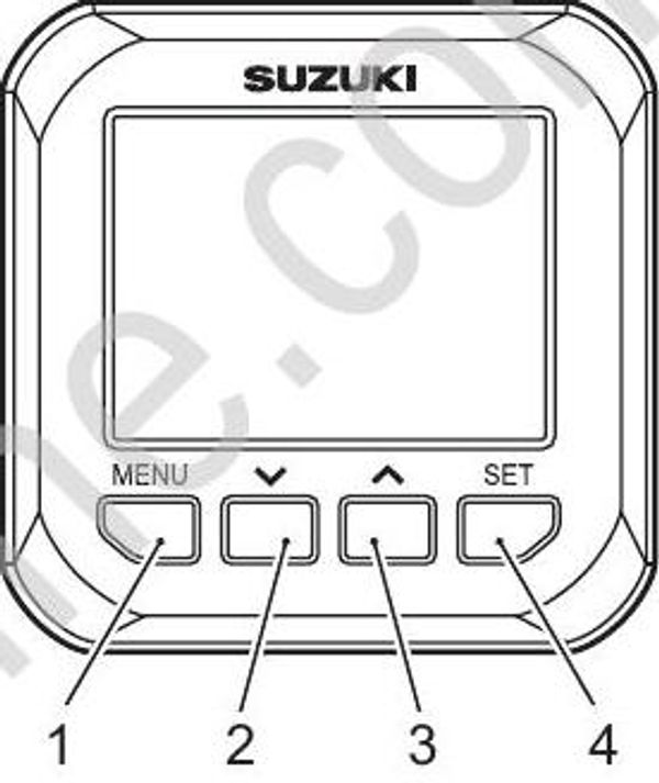
- MENU button
- Down button
- Up button
- SET button
Code for Self-Diagnostic System Operation
| Failed item | Code | Fail-Safe system active |
|---|---|---|
| MAP sensor 1 | 3 – 4 | Yes |
| Cylinder temp. sensor | 1 – 4 | Yes |
| IAT sensor | 2 – 3 | Yes |
| Exhaust manifold temp. sensor | 1 – 5 | Yes |
| Trim sensor | 3 – 7 | No |
| Throttle position sensor | 2 – 1 | Yes |
| Shift position sensor | 1 – 2 | No |
| Rectifier/Regulator (Over-charging) | 1 – 1 | No |
| Fuel injector | 4 – 3 | No |
| CKP sensor | 4 – 2 | No |
| CMP sensor 1 | 2 – 4 | No |
| CMP sensor 2 (VVT) | 2 – 6 | Yes |
| Air intake system | 2 – 2 | Yes |
| MAP sensor 2 (Pressure detect passage) | 3 – 2 | No |
| Neutral switch | 3 – 3 | No |
| VVT advance | 5 – 1 | Yes |
| Oil pressure switch | 5 – 3 | No |
| Oil control valve | 6 – 1 | No |
| ETV ECM | 7 – 1 | Yes |
| ETV Motor | 7 – 2 | Yes |
| ETV | 7 – 3 | Yes |
| Sub BCM | 7 – 4 | Yes |
| DBW system | 7 – 5 | No |
| ESA ECM | 8 – 1 | No |
| ESA motor | 8 – 2 | No |
| ESA | 8 – 3 | No |
| Knock sensor | 5 – 4 | Yes |
| O2 Sensor | 3 – 6 | Yes |
| O2 Sensor heater | 6 – 3 | Yes |
| Model distinction switch | 4 – 1 | Yes |
| Keyless system authentication error | 9 – 4 | No |
| keyless system communication error | 9 – 5 | No |
| Keyless system failure | 9 – 6 | No |
• If more than one failed items exist, the self-diagnostic system shows the failures in the order of their occurrence, one at a time, when any of gauge button is pressed. After confirming all failed item, “Check Engine X-X” indication will be cleared. However, the caution alarm icon is displayed until the cause is eliminated.
• If the failed item remains, the self-diagnostic indication appears again after turning the main switch “ON”.
• After correcting failed item, the self-diagnostic indication appears until the ECM receives the proper signal with the engine running or turn on the main switch from OFF.
• It is the basic theory that the cancellation of self-diagnostic indication is automatically performed when the failure is corrected and then supplying power to the ECM or operating the motor to receive a normal signal from sensor, switch, etc. by the ECM. However, in addition to the above, it has to meet the following conditions.
– The period of 20 – 30 seconds which is necessary for the ECM to decide the signal is normal.
– In the case of the codes 5-1 “VVT advance” or 6-1 “oil control valve”, it is necessary to operate the VVT system actually. So it is required to operate the motor at around 3 500 r/min for a certain period. However, the self-diagnostic code remains until the ECM decides the input signal during cruising.
The rectifier/regulator self-diagnostic indication may not display (be canceled) by turning the main switch “ON” because the ECM detects only battery voltage, not charging output. Under this condition the buzzer will not sound and diagnostic code not appear. However, if the rectifier/regulator have failed, the self diagnostic indication will again appear after starting the engine.
Condition for Self-Diagnostic System Operation
| Failed item | Condition |
|---|---|
| MAP sensor 1 | • No signal (With engine running) • Receiving an out of range “37 – 860 mmHg (1.45 – 33.85 inHg) (0.2 – 4.5 V)” signal (With engine running) |
| Cylinder temp. sensor | • No signal • Receiving an out of range “–46 to +170 °C (–50.8 – +338.0 °F) (0.10 – 4.6 V)” signal |
| IAT sensor | • No signal • Receiving an out of range “–46 to +169 °C (–50.8 – +336.2 °F) (0.10 – 4.6 V)” signal |
| CKP sensor | • During the rotation of the predetermined crankshaft angle, the normal CKP sensor signal pattern is not received by the ECM. |
| CMP sensor 1 | • During four crankshaft rotations, the normal CMP sensor signal pattern is not received by the ECM. |
| Air intake system | • During the ECM’s receiving input of the complete close signal from the throttle position sensor, the engine operates at an abnormally high speed. (Criterion: 2 100 r/min minimum) |
| MAP sensor 2(Pressure detect passage) | • Receiving unchanging signal regardless engine speed change. • From TPS sensor, the full close signal is inputted, but from the MAP sensor, the signal voltage exceeds 2.0 V. |
| Rectifier/Regulator(Over-charging) | • Receiving 16 V or higher signal |
| Exhaust manifold temp. sensor | • No signal • Receiving an out of range “–46 to +170 °C (–50.8 – +338.0 °F) (0.10 – 4.6 V)” signal |
| Fuel injector | • No operation signal from the ECM |
| Throttle position sensor | • Receiving an out of range “0.5 – 4.5 V” TPS main sensor signal. • The addition of two output voltages of the main sensor and sub sensor makes outside the specified range. |
| Shift position sensor | • Receiving an out of range “0.2 – 4.8 V” signal. |
| CMP sensor (VVT) | • During two crankshaft rotation, 4 signals are not input to ECM. |
| VVT advance | • There is a large difference between the target advance angle and the actual advance angle. |
| Neutral switch | •While the shift sensor outputs the forward or reverse signal, the ECM receives input of the neutral signal from the neutral switch. |
| Oil control valve | • OCV not operating. |
| Oil pressure switch | • While the engine is stopped and the main switch is on, the ECM receives an “OFF” signal from the oil pressure switch. |
| Trim sensor | • Receiving an out of range “0.2 – 4.8 V” signal. |
| ETV ECM | • ECM electronic throttle control circuit failure |
| ETV motor | • Throttle valve actuator motor operation failure or its power supply system (throttle relay, etc.) failure. • Motor connector open • Motor power supply line open |
| ETV | • Throttle valve operation failure |
| Sub BCM | • Sub BCM communication error • Low sub BCM source voltage. • Sub BCM failure |
| Failed item | Condition |
|---|---|
| DBW system | •CAN communication error between BCM and ECM. • LPS error (ECM received an input signal from each sensor which was outside the range of 4.5 – 5.5 V as total of main sensor and sub sensor output voltage.).•Low BCM source voltage (less than 6 V). • BCM failure. • ECM failure. |
| ESA ECM | • ECM electronic shift control circuit failure. |
| ESA motor | • Electronic shift motor failure.•Motor connector open•Motor power supply line open |
| ESA | • Response failure ECM has detected the target LPS output voltage signal, but no change occurs in the input signal voltage from shift position sensor. |
| Knock sensor | • No signal • Receiving an out of range “0.55 – 4.39 V” signal. |
| O2 sensor | • The compensation value of fuel injection amount is more than the predetermined value while the O2 feedback is executed. • The compensation value of fuel injection amount is below the predetermined value while the O2 feedback is executed. |
| O2 sensor heater | • No operation signal comes from the ECM. (Open or short in O2 sensor heater circuit) |
| Model distinction switch(Select terminal) | • The diagnostic code for model discrimination is displayed when a failure (either open or short circuit) exists in No.2 terminal of the wiring harness/connector. |
| Keyless system authentication error | • ECM detected that its ID code does not correspond with the ID code registered in the keyless control unit. |
| Keyless system communication error | • The ECM cannot receive CAN communication information from keyless control unit.(Faulty wire harness of keyless start system.) |
| Keyless system failure | • There is an irregularity on the internal circuit of the keyless control unit. |
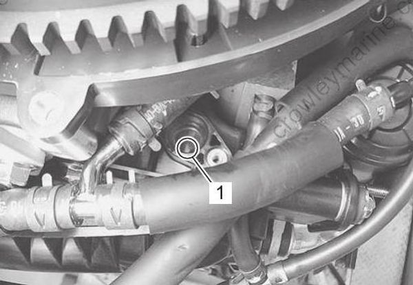
Failed item “MAP sensor 2” condition will be caused by clogged pressure detect passage (1) in intake manifold assembly.
Fail-Safe System Description
The fail-safe system is closely related to the self-diagnostic system.
When an abnormality occurs in a sensor signal, the ECM ignores the out-of-range signal and assumes a pre-programmed value for the failed sensors.
This allows the engine to continue running under the fail-safe condition.
Pre-Programmed Value for Fail-Safe System
| Failed item | Pre-Programmed value |
|---|---|
| MAP sensor 1 | • 240 – 760 mmHg / (9.4 – 30 inHg.) (The control takes place in accordance with the engine speed.) • VVT advance is fixed at the most retarded angle. |
| Air intake system | • The control is executed with the maximum engine speed as 2 000 r/min. |
| Cylinder temp. sensor | 60 °C (140 °F) |
| IAT sensor | 45 °C (113 °F) |
| Exhaust manifold temp. sensor | 60 °C (140 °F) |
| Throttle position sensor | • The throttle opening is fixed to default with the throttle motor relay turned off.ECM controls the engine speed at the maximum of 2 000 r/min by operating the remote control lever. |
| Shift position sensor | • ECM detects the shift position as neutral even under in-gear condition and controls the engine speed to idling. • If the “Throttle only” button is pressed with the remote control lever in neutral, the engine speed can be controlled at the maximum of 2 000 r/min by operating the lever. |
| CMP sensor (VVT) | • VVT advance is fixed at the most retarded angle. |
| VVT advance | • VVT advance is fixed at the most retarded angle. • The ECM cyclically outputs the drive and stop signals for the OCV and when the difference between the VVT’s target advance angle and the actual advance angle has come to the normal range, the diagnostic code display is canceled. |
| Trim sensor | • The control is continued with fixed sensor output as 3.5 V. |
| ETV ECM | • The throttle opening is fixed to default with the throttle motor relay turned off.ECM controls the engine speed at the maximum of 2 000 r/min by operating the remote control lever.(The engine rpm is controlled both by altering the ignition timing and skipping ignition for intermittent misfiring.) |
| ETV motor | • The throttle opening is fixed to default with the throttle motor relay turned off.ECM controls the engine speed at the maximum of 2 000 r/min by operating the remote control lever. |
| ETV | • The throttle opening is fixed to default with the throttle motor relay turned off. • ECM controls the engine speed at the maximum of 2 000 r/min by operating the remote control lever. |
| Sub BCM | • The main BCM controls the engine appropriately. |
| DBW system | • ECM causes the shift to return and fix to the neutral position and controls the engine speed to idling. |
| ESA ECM/ESA motor/ESA | • ECM turns off the shift motor relay and fixes the shift position to that when the failure occurred. The engine rpm is controlled with ECM at the maximum of 2 000 r/min by operating the remote control lever. |
| Knock sensor | • The ignition timing delays with the predetermined amount. |
| O2 sensor | • The fuel injection amount is controlled with the base map.(The O2 feedback can not be executed.) |
| O2 sensor heater | • The fuel injection amount is controlled with the base map.(The O2 feedback can not be executed.) |
| Model distinction switch(Select terminal) | • The original model (rotation) discrimination is retained. • The state that ECM is memorizing now is continued. |
There is no back-up system for the ECM itself. The engine will stop if it has failed.
Oil Change Reminder System Description
This system informs the operator of the time for replacing ENGINE OIL on the basis of the recommended maintenance schedule.
When the total motor operating hours have reached the preprogrammed hours, the “Change Oil” appears on the gauge screen, the buzzer will begin a series of double beeps if engine is not running (but main switch is ON). The above mentioned indication will repeat until the activated system is manually cancelled.
Indication of System Activation
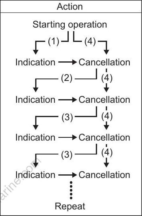
- Lapse of initial 20 hour’s operation
- Lapse of 80 hour’s operation
- Lapse of 100 hour’s operation
- When performing cancellation before system activation
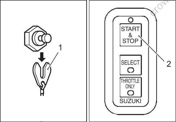
Cancellation Procedure
Turn the main switch key to “ON” position.
Pull out the emergency stop switch plate (1).
Depress the START & STOP button (2) three times in ten seconds.
A short beep will be heard if cancellation is successfully finished.Turn the main switch key to “OFF” position.
Set the switch plate (1) in original position.
• Canceling of the system activation is possible regardless of whether or not the engine oil has been replaced. Once the system has operated, however, SUZUKI strongly recommends that the engine oil be replaced before canceling the system activation.
• Even if the engine oil has been replaced with the system not operating, it is still necessary to perform the cancellation.
Water in Fuel Alert System Description
This engine is equipped with an integral fuel filter/water separator and associated alert system.
The alert system will activate if water separated from the fuel exceeds a specific volume.
If this system activates, the “Water in Fuel” and caution alarm icon (1) will display at all time and a buzzer will sound when the engine is in neutral only.
If this system activates, stop the engine, and check the fuel filter/water separator for water.
For inspection and cleaning of the fuel filter, refer to the “Low Pressure Fuel Filter Inspection” in Section 0B (Page 0B-17) and “Water Detection Switch Inspection” in Section 1G (Page 1G-31).
Multi function gauge
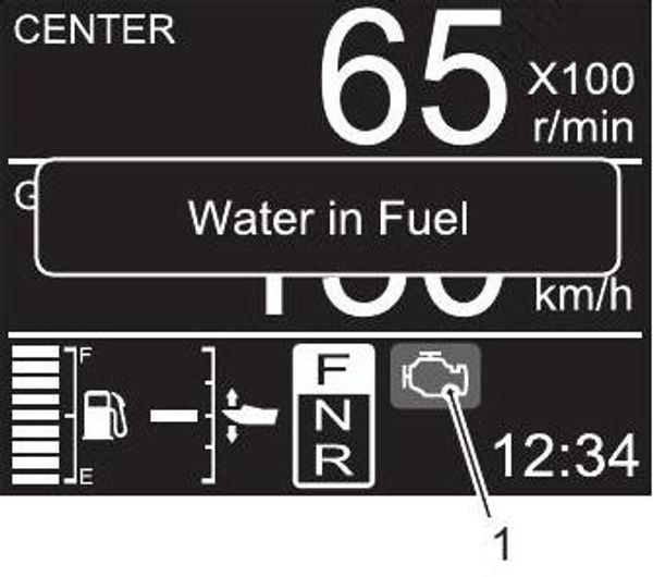
- Caution alarm icon
Troll Mode System Description
The troll mode system consists of the troll mode switch, ECM and BCM and related electrical wiring.
The “Troll Mode System” is activated by pressing the troll mode switch, when the motor is running at ingear idle speed. By using this system, you can set and maintain a desired engine speed with the control switch in a range from in-gear idle speed (approx. 650 r/min) to 1 200 r/ min.
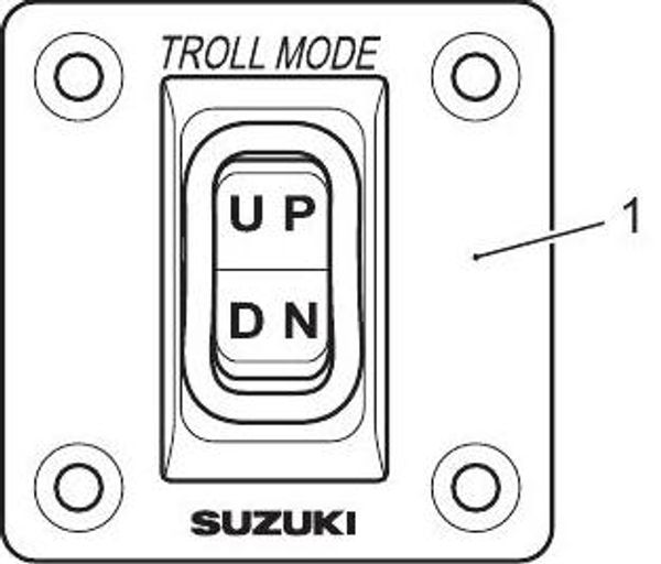
- Troll mode switch
For the multiple engines: In-gear idle speed of all engines is controlled at the same time.
During Troll mode, ECM will control the engine speed as follows:
The switch signal is inputted to ECM through BCM.
ECM calculates the target engine speed with the input signal from the switch, then controls the throttle motor and the trolling speed is made to become to the target speed.
How to Use The Troll Mode
Setting the troll mode:
Shift into forward or reverse gear and make sure that the throttle is fully closed (in-gear idle speed).
Press the “UP” or “DN” position of the troll mode switch, until you hear one beep.
• This system will not function properly until engine is at normal operating temperature.
• The troll mode system will not operate if the switch is depressed when the remote control lever is in the neutral position.
• For the multiple engines: If the throttle of all engines are fully closed and one of engines is in-gear, it shifts to the troll mode when the switch is depressed.
Adjusting trolling speed:
When pressing the “UP” switch, one short beep sounds and the engine speed increases by 50 r/min.
When pressing the “DN” switch, one short beep sounds and the engine speed decreases by 50 r/min.
• When pressing the “DN” switch at the lower limit of trolling speed of all engines, the engine speed will not change and three long (0.8 sec.) beeps will sound.
• When pressing the “UP” switch at the upper limit of trolling speed of all engines, the engine speed will not change and three long (0.8 sec.) beeps will sound.
• For the multiple engines: If the switch is operated when one engine has reached the adjustment limit of trolling speed, while any other engine has not, one short beep sounds and the rpm of engine which has not reached the adjustment limit changes.
• Shift operation and throttle control remain operational, even in troll mode.
Cancelling the troll mode:
The troll mode can be cancelled by shifting the all remote control levers to the neutral position, or by increasing the engine speed to 3 000 r/min or more. In both cases, two short (0.1 sec.) beeps sound when cancelling the troll mode.
Selective Rotation System Description
Lower unit of this product can be used for both regular rotation or counter rotation without changing itself.
ECM (engine control module) is used for detecting the conditions of ECM No. 2 terminal whether its circuit is open (OFF) or grounded (ON); and for controlling the rotating direction of the shift actuator (motor) depending on the detected condition.
The selection of this circuit selects either from two types of rotation select connectors, and installs it in the select terminal.
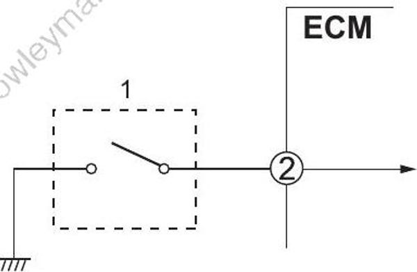
- Select connector / terminal
ECM controls the shift actuator by means of the rotation select connector in the following manner:
- Connection of regular rotation select connector to select terminal will open terminal No. 2, and this controls the actuator to become regular rotation lower unit.
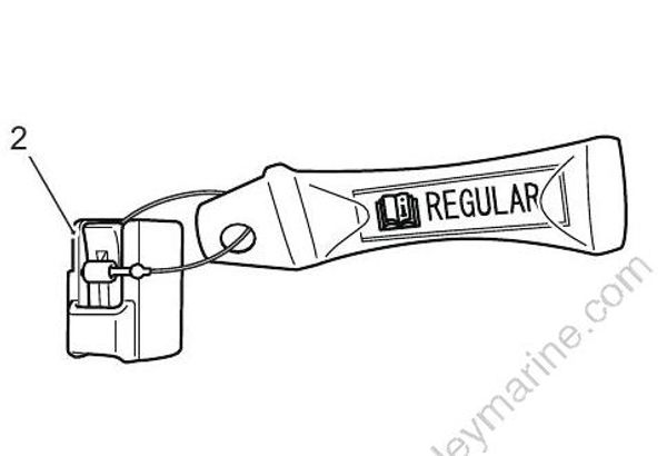
- Regular select connector
- When counter rotation select connector is connected to select terminal, terminal No. 2 will be grounded, and this controls the actuator to become counter rotation lower unit.
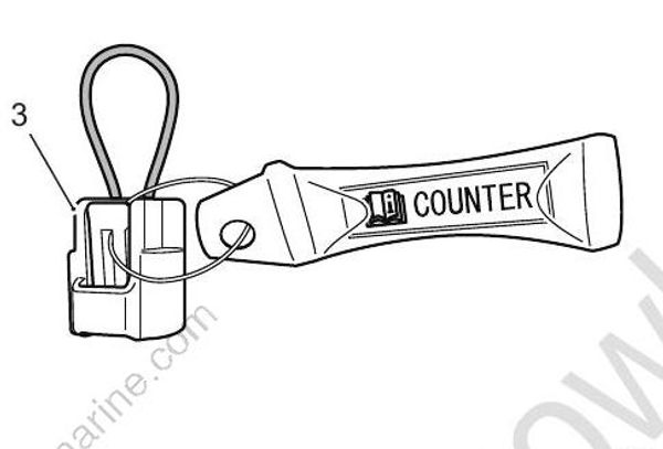
- Counter select connector (Optional part)
ECM detects the status of rotation select connector (whether it is set to regular or counter) immediately after turning the main switch to ON position, and determines the rotating direction of the shift actuator. From thereon, no judgment will be made for determining the rotating direction of the actuator. (Even when the connecting position of the rotation select connector is changed, the rotating direction of the shift actuator will not be changed.) For changing the rotating direction of the shift actuator, the rotation select connector must be replaced when the main switch is in OFF position.
To change the rotation from regular rotation to counter rotation:
Turn the main switch OFF before connecting or disconnecting the select connector.
Turn the main switch to OFF position.
Wait for one minute until the ECM internal circuit is turned OFF.
Remove the motor cover.
Disconnect the blue regular rotation select connector located near the fuse box.
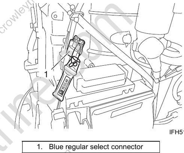
- Blue regular select connector
- Connect the white counter select connector.
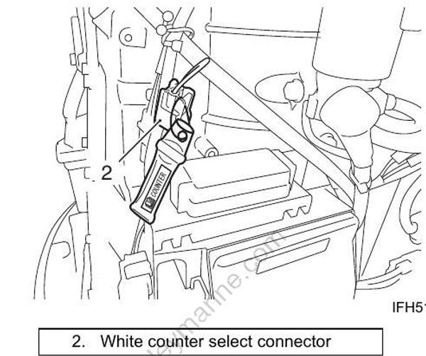
To return the rotation to regular rotation:
Turn the main switch to OFF position.
Wait for one minute until the ECM internal circuit is turned OFF.
Remove the motor cover.
Disconnect the white counter select (optional) connector located near the fuse box.
Connect the blue regular rotation select (standard) connector.
Keyless Start System Description
The keyless start system uses a coded key fob to transmit an access code to the engine’s starting system.
The engine can be started without operating a mechanical key when the key fob is located within a 1 m (39.3 in) radius of the keyless control unit.
The keyless start system consists of a key fob, keyless control unit, ECM, power relay, main switch, and related wiring. Radio communication is performed between the key fob and the keyless control unit.
The keyless control unit and ECM are connected by a CAN communication bus to exchange information through CAN communication.
The system operates by means of radio communication by cross-checking the ID code of the key fob, keyless control unit and ECM.
When the ID codes between the key fob, keyless control unit and ECM match, the power relay turns ON to supply voltage to the engine control system, enabling the engine to be started.
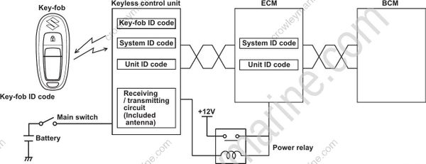
Function of component parts
| Main key | The main knob key is used for pairing the key-fobs and powering the system. |
|---|---|
| Emergency key | The emergency key is used to create a pass code and to enter the pass code to start the engine(s) when all key-fobs have been lost or misplaced. |
| Key fob | Transmits ID code signal to keyless control unit. |
| Keyless control unit | Transmits its ID code to ECM. |
| ECM | • Check keyless control unit ID code. • Transmit its ID code to keyless control unit. |
Shifting to keyless start system ON
With the key fob within the 1 m (39.3 in) radius, turn and release the main switch knob from “Neutral” to ON/OFF position:
First: The ID code of the key fob and the ID code registered in the keyless control unit are cross checked.
When both ID codes match, communication for cross-checking the key fob comparison is terminated.Second: The system ID codes are cross-checked for comparison between the keyless control unit and ECM.
The functions of ECM are enabled by matching the system ID codes.Third: Registered unit ID codes are cross-checked between the keyless control unit and the ECM. When both unit ID codes match, the power relay turns ON and the ECM enters engine start standby mode.
When the cross-check is complete, the engine is enabled to start (cranking, ignition, and injection). If not, the system power is turned OFF.
Shifting from keyless start system ON to OFF
When the key fob and the keyless control unit are within the communication range, the keyless start system turns OFF after 30 seconds if the main switch knob is turned from neutral to ON/OFF and release knob.
It takes about one minutes for the ECM internal circuit to turn OFF.
When the key fob is outside the communication range of the keyless control unit, the keyless start system is locked.
Emergency start
As a backup in case the key fob is not available, the system can be put into engine start standby mode by entering a passcode using the emergency mechanical key.
Immobilizer system
The engine can be started only when the key fob ID code corresponds with the registered code in keyless control unit.
Multi-Stage Induction Description
Outline
The multi-stage induction system is designed to improve the intake efficiency by changing the intake tract volume in accordance with the engine speed.
This system improves low and mid range torque and increases power output at the higher rpm ranges.
System Composition
The intake manifold assembly provides air for the low/ mid range intake tract and high speed range tracts.
Mounted on the intake manifold are throttle body, VSV (Vacuum Switching Valve), vacuum tank, depression chamber for operating the system and the shut off valve for switching the intake tract. System connection components include one check valve and hose to form the vacuum passage.
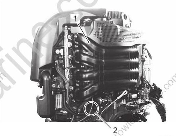
- Intake manifold assembly
- Check valve
Vacuum tank
The vacuum tank stores vacuum created during engine operation. The vacuum tank’ purpose is to supply a stable vacuum to the depression chamber under the varying vacuum conditions normally occurring within the intake manifold, thereby making it possible to control the shut off valve accurately.
A hose and check valve connects one side of the vacuum tank to the intake manifold. The other side of the tank is connected to the VSV with a hose.
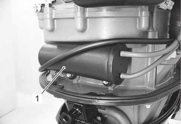
- Vacuum tank
VSV (Vacuum Switching Valve)
One side of the VSV is connected via hose to the vacuum tank, the other side is connected via hose to the depression chamber.
The VSV receives operating signals from the ECM.
When the ECM signals OFF, the VSV releases vacuum to the atmosphere.
When the ECM signals ON, the VSV supplies vacuum to the depression chamber.
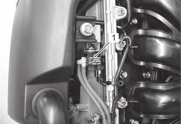
- VSV (Vacuum switching valve)
Depression chamber
The depression chamber is designed to open/close the shut off valve.
When vacuum is applied to the depression chamber, the rod in the chamber is pulled in closing the shut off valve. When vacuum is not applied to the chamber, the rod returns to the original position, opening the shut off valve.
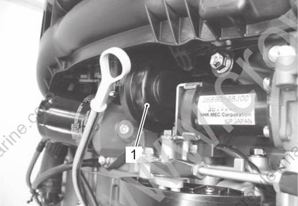
- Depression chamber
System operation
This system is operated by the vacuum created during engine operation and controlled by the ECM.
To operate the system (open/close the shut off valve to change the intake tract), the intake manifold, check valve, vacuum tank, VSV and depression chamber are connected with hoses as shown in the illustration. A rod is used to connect the shut off valve and depression chamber for opening and closing the valve.
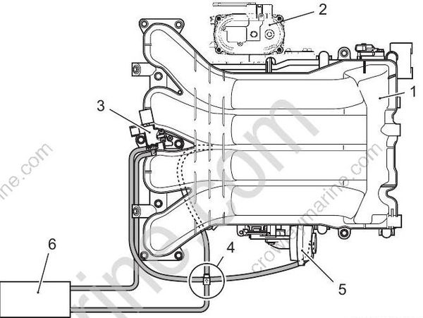
- Intake manifold1
- Electronic throttle body
- VSV
- Check valve
- Depression chamber
- Vacuum tank
Low & mid speed range
When engine speed is below the preset value (*), the ECM generates a signal to turn the VSV ON, applying vacuum to the depression chamber which closes the shut off valve.
With the valve closed during the engines low to mid speed range, intake air is supplied through the low and mid speed intake tract only.
In this operating mode, intake air speed is boosted and, combined with the inertia effect to the long intake tract, increases low and mid speed range engine torque.
*: Preset value;
DF200AP: Approx. 4 300 – 4 500 r/min
Low and Mid speed
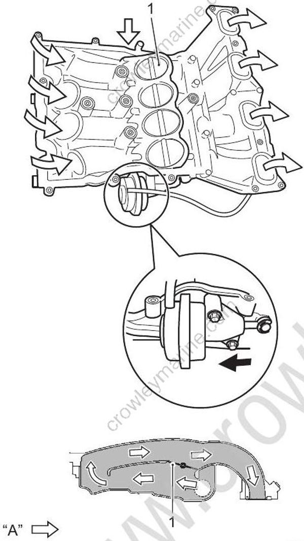
- Shut off valve
“A”: Air flow
High speed range
When the engine speed is above the preset value (*), the ECM generates a signal to turn the VSV OFF, and vacuum is no longer applied to the depression chamber. Without vacuum the shut off valve return spring returns and holds the valve in its normal open position.
In this operating mode, intake air is supplied to the engine through the high speed intake tract only.
This enlarges the intake tract volume, improves intake inertia and efficiency, which increases the engines output power.
High speed
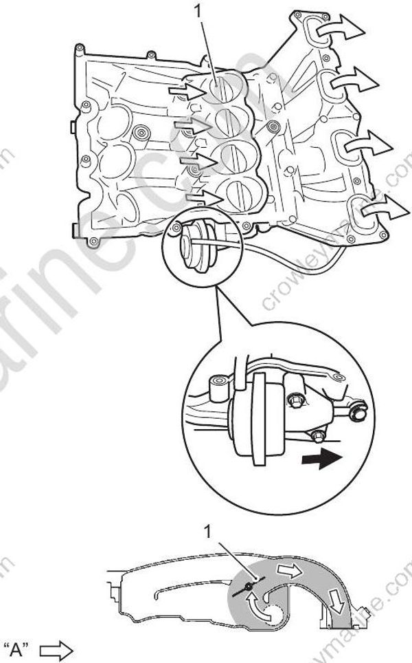
- Shut off valve
“A”: Air flow
VVT (Variable Valve Timing) System Description
The VVT system is designed to continuously vary intake valve timing to best fit the engines current operating condition.
The intake cam timing sprocket assembly (VVT actuator) is located at the front end of the intake camshaft. The timing sprocket’ internal rotor is operated by engine oil pressure. Since the rotor and intake camshaft is bolted together, the rotor and camshaft move together. Varying the intake valve timing is accomplished by changing the intake camshaft phase angle relative to the intake cam timing sprocket using pressurized engine oil applied to the rotor through an ECM controlled oil control valve.
The oil control valve (OCV) directs engine oil pressure to the advance chamber or retard chamber inside the intake cam timing sprocket assembly (VVT actuator). The oil control valve operates on a duty cycle controlled by the ECM.
The ECM determines the optimum valve timing (advance angle) under various operating conditions based on engine speed, manifold pressure (throttle opening) and cylinder wall temperature. These input values are then used to control the position of the oil control valve (OCV). The ECM also detects the actual advance angle from the CMP sensor inputs to perform feedback control and accurately maintain the target advance angle.
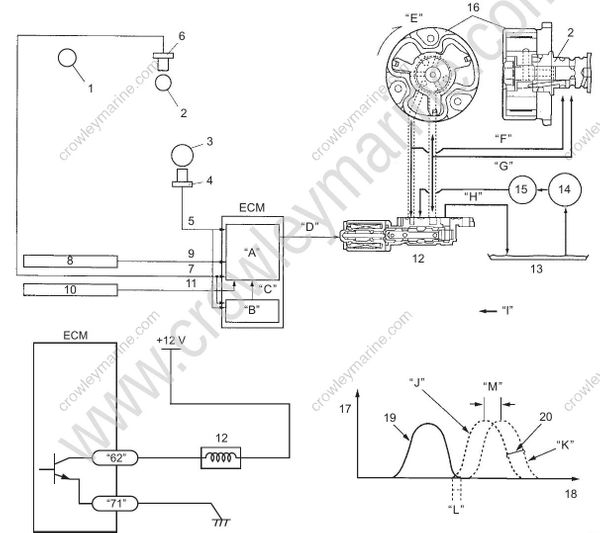
- Ex. camshaft
- In. camshaft
- Crankshaft
- CKP sensor
- Crank position
- CMP sensor 2
- Cam position signal
- Cylinder temp. sensor
- Cylinder temp. signal
- MAP sensor
- Manifold pressure signal
- Oil control valve (OCV)
- Oil pan
- Oil pump
- Oil filter
- VVT actuator
- Valve lift
- Crank angle
- Ex. valve
- In. valve
“A”:Target advance
“B”:Actual valve timing
“C”:Feed back
“D”:Duty control
“E”:Rotation direction
“F”:Retard pressure
“G”:Advance pressure
“H”:Drain
“I”:Engine oil pressure
“J”:Advance
“K”:Retard
“L”:Valve overlap
“M”:40° movable angle
OCV (Oil Control Valve)
The OCV is used to regulate oil flow and is installed on the lower camshaft housing.
Retard Operation
When the duty ratio of the ECM is small, the OCV spool valve is pushed away from the coil by spring force and engine oil pressure is applied to the retard chamber.
Engine oil remaining in the advance chamber is drained out through the spool valve.
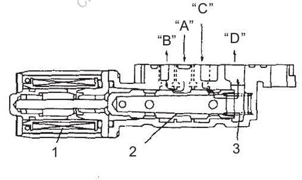
1.Coil
2.Spool valve
3.Spring
A”:Engine oil pressure
“B”:To retard chamber
“C”:To advance chamber
“D”:Drain
Advance Operation
When the duty ratio of the ECM is large, the spool valve is pulled towards the coil by magnetic force, compressing the spring and applying engine oil pressure to the advance chamber side.
Engine oil remaining in the retard chamber side is drained out through the spool valve.
Retaining Operation
When the duty ratio of the ECM is medium, the OCV coil’ magnetic and return spring forces are equal. This positions the spool valve between the advance and retard chamber, closing both oil passages.
Intake Cam Timing Sprocket Assembly
Inside the intake cam timing sprocket assembly (VVT actuator), there are separate advance and retard chambers formed by a partition of the rotor.
The rotor moves inside the housing as engine oil pressure is applied to the advance or retard chamber. The intake cam timing sprocket is part of the sprocket housing assembly. Since the rotor and intake camshaft are bolted together, when the rotor moves inside the housing, a change of phase angle takes place in the relative position between the intake camshaft and intake cam timing sprocket. The rotor has a spring pressured lock pin which engages with the housing when spring force is greater than oil pressure, locking the rotor in the most retarded position. This prevents a change of phase angle between the intake camshaft and intake cam timing sprocket when the engine oil pressure is low at engine start.
When the engine is started and the engine oil pressure is applied to the advance chamber, the lock pin is forced up, compressing the return spring, releasing the rotor and allowing the VVT actuator to function.
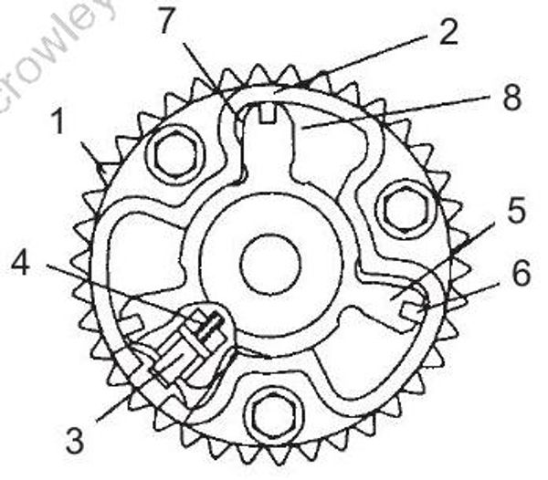
- Intake cam timing sprocket
- Housing
- Lock pin
- Spring
- Rotor
- Seal
- Advance chamber
- Retard chamber
Component Location
Engine Control System Components / Engine Electrical Device Location
Refer to “Wiring Harness Routing Diagram” in Section 4A (Page 4A-4).
Diagnostic Information and Procedures
ECM Power and Ground Circuit Check
Wiring Diagram
Normal key start model
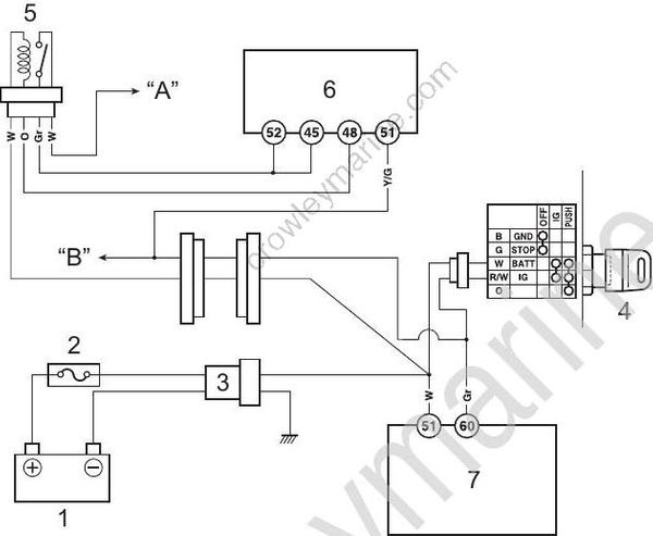
1.Battery
2.30 A fuse
3.Sub battery cable
4.Main switch
5.ECM main relay
6.ECM
7.BCM
“A”:To 30 A main relay fuse
“B”:To neutral switch
Keyless start model
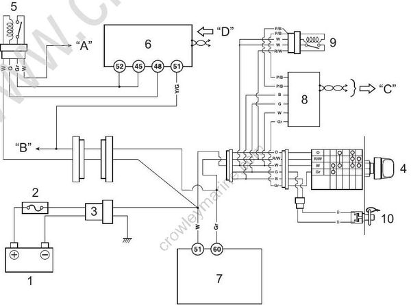
1.Battery
2.30 A fuse
3.Sub battery cable
4.Main switch
5.ECM main relay
6.ECM
7.BCM
8.Keyless control unit
9.ECM power relay
10.Emergency stop switch
“A”:To 30 A main relay fuse
“B”:To neutral switch
“C”:To ECM
“D”:From keyless control unit
Circuit Description
The source voltage is supplied to BCM and ECM each through the two system lines.
From the battery, the source is inputted to BCM No.51 terminal through the sub battery cable.
When the main switch is turned on:
The source is supplied to BCM No.60 terminal through R/W line of the main switch.
ECM main relay turns on and battery voltage is supplied to ECM No.45, 52 terminals through the main relay.
Ensure battery cable connection are clean and secure. Failure at the battery connection will cause incorrect operation of BCM and ECM.
Troubleshooting
Step 1
Is operation of the main relay heard when the main switch is turned “ON”?
Yes Go to step 4.
No Go to step 2.
Step 2
**Are the main fuses (60 A and 30 A, for ignition and ECM) and sub battery cable fuse (30 A) in good condition? **
Yes Go to step 3.
No Replace.
Step 3
Disconnect the ECM connectors at the ECM with the main switch “OFF”.
Measure the voltage between the No.48 terminal of the ECM connector and body ground.
Is the voltage 12 V (Battery Voltage)?
Yes Go to step 4.
No * Check the ECM main relay. Refer to “ECM Main Relay Inspection” (Page 1A-85).
- Poor ECM main relay connection.
- “O” wire open, shorted or poor connection.
Step 4
Turn the main switch “OFF”.
Connect the 26-pin and 34-pin test cord set between the ECM and the main wire harness.
Turn the main switch “ON”.
Measure the voltage between the No.51 terminal and body ground.
Is the voltage 12 V (Battery Voltage)?
Yes Go to step 5.
No * Check the main switch. Refer to “Main Switch Inspection” in Section 1I (Page 1I-15).
- “Gr”, “Y/G” wire open circuit or poor connection.
- Faulty ECM power relay. (Keyless start model)
Step 5
Turn the main switch “OFF”.
Connect the 26-pin and 34-pin test cord set between the ECM and the main wire harness.
Turn the main switch “ON”.
Measure the voltage between the No.48 terminal and body ground.
Is the voltage approx. 0.8 V?
Yes Go to step 6.
No * “O” wire open, shorted or poor connection.
- If the wiring and connection is OK, intermittent trouble or a faulty ECM may be the cause.
Step 6
Turn the main switch “ON”.
Measure the voltage between the No.45 and No.52 terminal and body ground.
Is the voltage 12 V (Battery Voltage)?
Yes ECM power and ground circuit are in good condition.
No * “Gr” wire open, shorted or poor connection.
- Faulty ECM main relay.
Troubleshooting with Self-Diagnostic Code
Before troubleshooting, read and follow the “Precautions on Engine Control Diagnosis” (Page 1A-1).
In this section, troubleshooting procedures are based on the assumption that the “low pressure fuel system” and “mechanical components (power unit, lower unit, etc.)” are normal.
Self-Diagnostic Code “3 – 4” MAP Sensor
Wiring Diagram
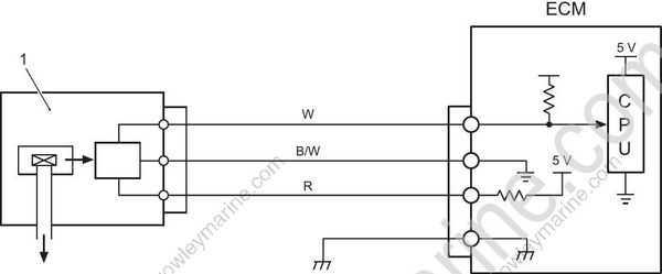
- MAP sensor
Troubleshooting
Step 1
Remove the fuel hose guard.
With the main switch “OFF”, disconnect the MAP sensor connector.
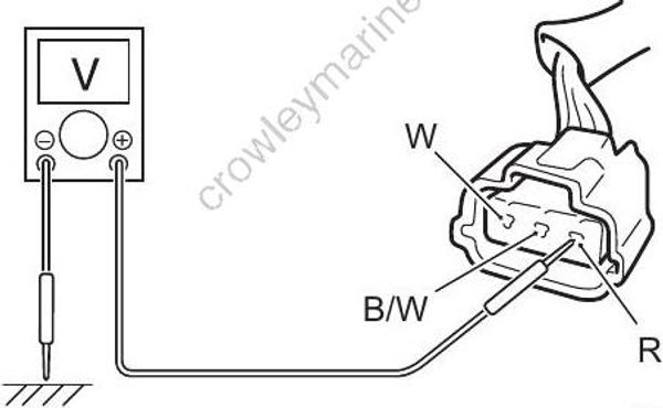
With the main switch “ON”, check the voltage at the “R” wire terminal of the MAP sensor connector.
Is the voltage approx. 4 – 5 V?
Yes Go to step 2.
No • “R” wire open, “R” wire shorted to ground or a poor wire connection.
• If the wiring and connection is OK, substitute a known-good ECM and recheck.
Step 2
- Check the MAP sensor output voltage change. Refer to “MAP Sensor Output Voltage Inspection” in Section 1C (Page 1C-16).
Is it in good condition?
Yes • Substitute a good ECM and recheck.
No • Faulty MAP sensor.
• “R” wire shorted to “W” wire, “B/W” wire open, poor “B/W” wire connection, poor
“W” wire connection, “W” wire open or poor MAP sensor connection.
• If the wiring and connection is OK, intermittent trouble or a faulty ECM may be the cause.
Self-Diagnostic Code “1 – 4” Cylinder Temp. Sensor
Wiring Diagram
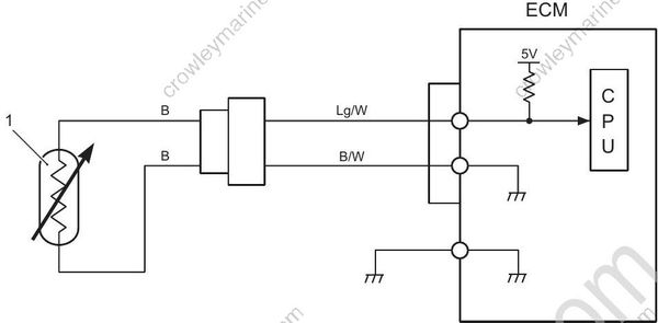
- Cylinder temp. sensor
Troubleshooting
Step 1
With the main switch “OFF”, disconnect the cylinder temp. sensor lead wire connector.
With the main switch “ON”, check the voltage at the “Lg/W” wire terminal of the cylinder temp. sensor connector.
Is the voltage 4 V or more?
Yes Go to step 2.
No * “Lg/W” wire shorted to the “B/W” wire or ground circuit.
- If the wiring is OK, substitute a known-good ECM and recheck.
Step 2
- Check the cylinder temp. sensor.
Refer to “Cylinder Temp. Sensor Inspection” in Section 1C (Page 1C-11).
Is it in good condition?
Yes Poor cylinder temp. sensor connection, intermittent trouble or a faulty ECM may be the cause.
No Faulty cylinder temp. sensor.
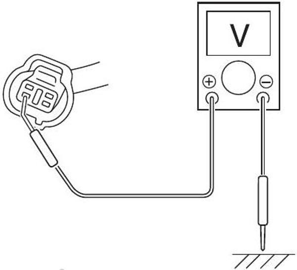
For step 1
Self-Diagnostic Code “2 – 3” IAT Sensor
Wiring Diagram
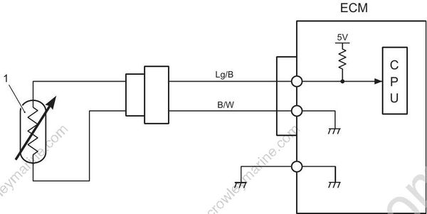
- IAT sensor
Troubleshooting
Step 1
With the main switch “OFF”, disconnect the IAT sensor connector.
With the main switch “ON”, check the voltage at the “Lg/B” wire terminal of the IAT sensor connector.
Is the voltage 4 V or more?
Yes Go to step 2.
No * “Lg/B” wire shorted to “B/W” wire or ground circuit.
- If the wiring is OK, substitute a known-good ECM and recheck.
Step 2
- Check the IAT sensor.
Refer to “IAT Sensor Inspection” in Section 1C (Page 1C-14).
Is it in good condition?
Yes Poor IAT sensor connection, intermittent trouble or a faulty ECM may be cause.
No Faulty IAT sensor.
For step 1
Self-Diagnostic Code “1 – 5” Ex. Manifold Temp. Sensor
Wiring Diagram
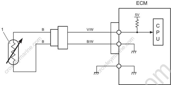
- Ex. manifold temp. sensor
Troubleshooting
Step 1
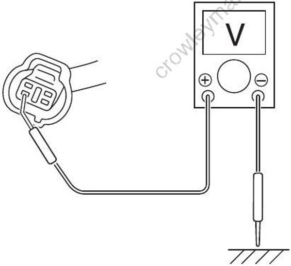
With the main switch “OFF”, disconnect the Ex. manifold temp. sensor lead wire connector.
With the main switch “ON”, check the voltage at the “V/W” wire terminal of the Ex. manifold temp. sensor connector.
Is the voltage 4 V or more?
Yes Go to step 2.
No * “V/W” wire shorted to “B/W” wire or ground circuit.
- If the wiring is OK, substitute a known-good ECM and recheck.
Step 2
- Check the Ex. manifold temp. sensor.
Refer to “Ex. Manifold Temp. Sensor Inspection” in Section 1C (Page 1C-12).
Is it in good condition?
Yes Poor Ex. manifold temp. sensor connection, intermittent trouble or a faulty ECM may be the cause.
No Faulty Ex. manifold temp. sensor.
For step 1
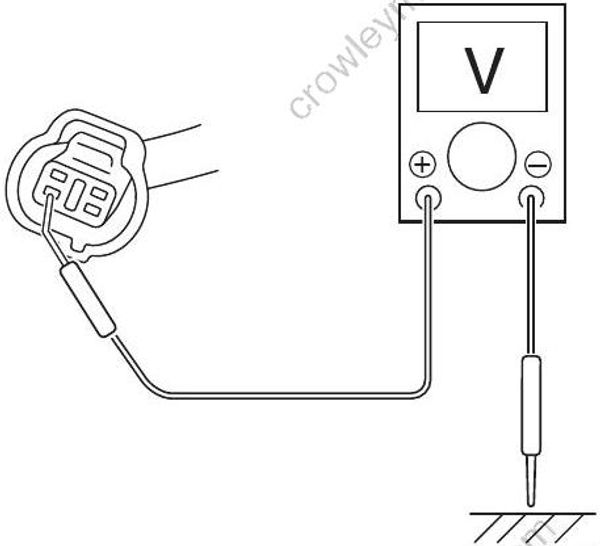
Self-Diagnostic Code “3 – 7” Trim Sensor
Wiring Diagram
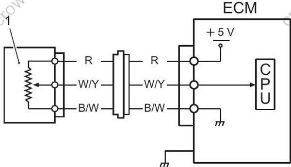
- Trim sensor
Troubleshooting
Step 1
With the main switch “OFF”, disconnect trim sensor connector.
With the main switch “ON”, check the voltage at the “R” wire terminal of trim sensor connector.
Is the voltage approx. 4 – 5 V?
Yes Go to step 2.
No * “R” wire open, “R” wire shorted to ground circuit or poor wire connection.
- If the wire and connection is OK, substitute a known-good ECM and recheck.
Step 2
- Check the trim sensor output voltage change.
Refer to “Trim Sensor Inspection” in Section 1C (Page 1C-36).
Is it in good condition?
Yes Poor trim sensor connection, intermittent trouble or a faulty ECM.
No * “R” wire shorted to “W/Y” wire, “B/W” wire open, poor “B/W” wire connection, poor “W/Y” wire connection, “W/Y” wire open or poor trim sensor connection.
If the wire and connection is OK, intermittent trouble or a faulty ECM may be the
cause.Faulty trim sensor.
*For step 1**
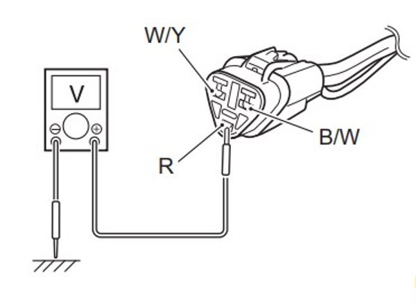
Self-Diagnostic Code “2 – 1” TPS (Throttle Position Sensor)
Wiring Diagram
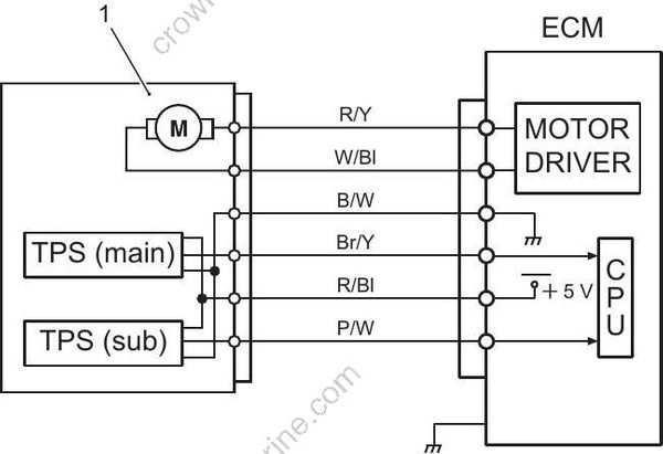
- Electronic throttle body
Troubleshooting
Step 1
Remove the fuel hose guard.
With the main switch “OFF”, disconnect the electronic throttle body connector.
With the main switch “ON”, check the voltage at the “R/Bl” wire terminal of the electronic throttle body connector.
Is the voltage approx. 4 – 5 V?
Yes Go to step 2.
No * “R/Bl” wire open, “R/Bl” wire shorted to ground circuit or poor connection.
- If the wiring and connection is OK, substitute a known-good ECM and recheck.
Step 2
- Check the TPS output voltage change.
Refer to “TPS Inspection” in Section 1C (Page 1C-31).
Is it in good condition?
Yes Substitute a known-good ECM and recheck.
No * Faulty TPS.
“R/Bl” wire shorted to “Br/Y” or “P/W” wire, “B/W” wire open, poor “B/W” wire connection, poor “Br/Y” or “P/W” wire connection, “Br/Y” or “P/W” wire open or poor TPS connection.
If the wiring and connection is OK, intermittent trouble or a faulty ECM may be the cause.
*For step 1**
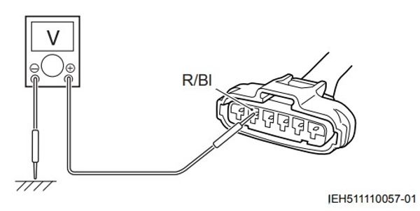
Self-Diagnostic Code “1 – 2” SPS (Shift Position Sensor)
Wiring Diagram
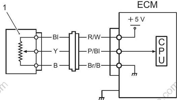
- SPS
Troubleshooting
Step 1
Remove lower side covers.
With the main switch “OFF”, disconnect the SPS lead wire connector.
With the main switch “ON”, check the voltage at the “R/W” wire terminal of the SPS lead wire connector.
Is the voltage approx. 4 – 5 V?
Yes Go to step 2.
No * “R/W” wire open, “R/W” wire shorted to ground circuit or poor connection.
- If the wiring and connection is OK, substitute a known-good ECM and recheck.
Step 2
- Check the SPS output voltage change.
Refer to “Shift Position Sensor Power Source and Output Voltage Inspection” in Section 1C (Page 1C-24).
Is it in good condition?
Yes Poor shift position sensor connection, intermittent trouble or a faulty ECM may be the cause.
No * Faulty SPS.
“R/W” or “Bl” wire shorted to “P/Bl” or “Y” wire, “Br/B” or “B” wire open, poor “Br/B” or “B” wire connection, poor “P/Bl” or “Y” wire connection, “P/Bl” or “Y” wire open or poor SPS connection.
If the wiring and connection is OK, intermittent trouble or a faulty ECM may be the cause.
*For step 1**
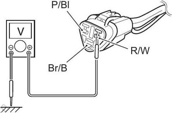
Self-Diagnostic Code “1 – 1” Rectifier / Regulator (Over Charging)
• This self-diagnostic code indication may be canceled when turning the main switch “ON” (engine not running), because ECM detects battery voltage.
• It is difficult to thoroughly check the rectifier/regulator. Before replacing it with new one, check that the ground point has good electrical contact.
Troubleshooting
Step 1
- Check the rectifier/regulator.
Refer to “Rectifier / Regulator Inspection” in Section 1K (Page 1K-9).
Is the result OK?
Yes Go to step 2.
No Faulty rectifier/regulator.
Step 2
- With the engine running, check charging voltage at idle speed.
Is the result 16 V or higher?
Yes Faulty rectifier/regulator.
No Faulty ECM or wire continuity/connection failure.
Self-Diagnostic Code “4 – 3” Fuel Injector
Wiring Diagram
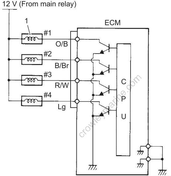
- Fuel injector
Troubleshooting
Step 1
- Using a sound scope, check that each injector has an operating sound when the engine is cranking.
Do all injectors make an operating sound?
Yes Fuel injector and its circuit are in good condition.
No Go to step 2.
Step 2
- Check the fuel injector, the wiring connection and the wire harness of the fuel injector not making the operating sound.
Are all of the above OK?
Yes Substitute a known-good ECM and recheck.
No • Faulty injector or its circuit.
• Go to step 3.
Step 3
- With the main switch “OFF”, disconnect the connectors from the fuel injectors.
- Check the voltage at “Gr” wire terminal with the main switch “ON”.
Is the voltage 12 V (battery voltage)?
Yes Go to step 4.
No Power circuit open.
Step 4
- Disconnect the ECM connectors with the main switch “OFF”, and check all of the injectors for resistance.
Refer to “Resistance Check” in Section 1C (Page 1C-9).
Is the resistance 10 – 14 Ω for each injector?
Yes Substitute a known-good ECM and recheck.
No Faulty injector or its circuit.
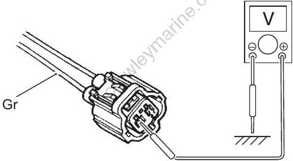
Self-Diagnostic Code “4 – 2” CKP Sensor
Wiring Diagram
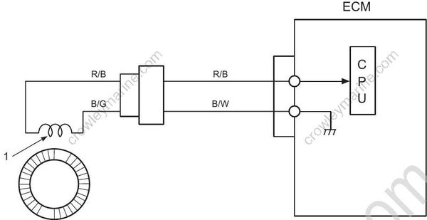
- CKP sensor
Troubleshooting
Step 1
- Check the CKP sensor air gap.
Refer to “CKP Sensor Removal and Installation” in Section 1C (Page 1C-13).
Is it in good condition?
Yes Go to step 2.
No Incorrectly adjusted air gap.
Step 2
- Check the CKP sensor resistance.
Refer to “Resistance Check” in Section 1C (Page 1C-9).
Is it in good condition?
Yes Open wire between the CKP sensor and the ECM, poor lead wire connection or sensor lead wires are shorted to each other. If lead wire and connection are OK, intermittent trouble or a faulty ECM may be the cause.
No Faulty CKP sensor.
Self-Diagnostic Code “2 – 4” CMP Sensor 1
Wiring Diagram
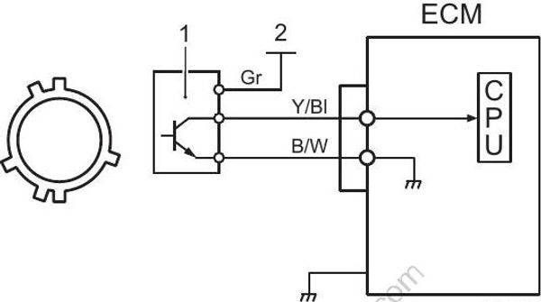
- CMP sensor 1
- 12 V (From main relay)
Troubleshooting
Step 1
Is the CMP sensor #1 installed properly and the wire harness connected securely?
Yes Go to step 2.
No Correct.
Step 2
With the main switch “OFF”, disconnect the connector from the CMP sensor #1.
Check for proper connection to the CMP sensor #1 at “Gr”, “Y/Bl” and “B/W” wire terminals.
If OK, turn the main switch “ON” and check the voltage at the “Gr”, “Y/Bl” and “B/W” wire terminals of the CMP sensor #1 connector.
CMP sensor #1 voltage
Terminal “Gr”: 10 – 14 V
Terminal “Y/Bl”: 4 – 5 V
Terminal “B/W”: 0 V
Is the voltage satisfactory?
Yes Go to step 5.
No Go to step 3.
Step 3
Was terminal “Y/Bl” voltage in step 2 within specification?
Yes Go to step 4.
No “Y/Bl” wire open or shorted to ground/power supply circuit. If the wiring and connection is OK, substitute a known good ECM and recheck.
Step 4
Was terminal “Gr” voltage in step 2 within specification?
Yes Go to step 5.
No “Gr” wire open circuit. If the wiring and connection is OK, substitute a known good ECM and recheck.
Step 5
Check the CMP sensor #1 and sensor trigger vane. Refer to “CMP Sensor Inspection” in Section 1C (Page 1C-15).
Is check result satisfactory?
Yes Substitute a known-good ECM andrecheck.
No Replace CMP sensor #1.
For step 2
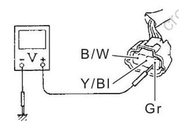
Self-Diagnostic Code “2 – 6” CMP Sensor 2 (VVT)
Wiring Diagram
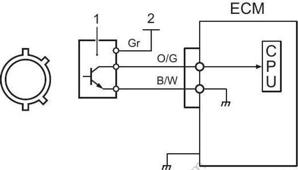
- CMP sensor 2
- 12 V (From main relay)
Troubleshooting
Step 1
Is the CMP sensor #2 installed properly and the wire harness connected securely?
Yes Go to step 2.
No Correct.
Step 2
With the main switch “OFF”, disconnect the connector from the CMP sensor #2.
Check for proper connection to the CMP sensor #2 at “Gr”, “O/G” and “B/W” wire terminals.
If OK, turn the main switch “ON” and check the voltage at the “Gr”, “O/G” and “B/W” wire terminals of the CMP sensor #2 connector.
CMP sensor #2 voltage
Terminal “Gr”: 10 – 14 V
Terminal “O/G”: 4 – 5 V
Terminal “B/W”: 0 V
Is the voltage satisfactory?
Yes Go to step 5.
No Go to step 3.
Step 3
Was terminal “O/G” voltage in step 2 within specification?
Yes Go to step 4.
No “O/G” wire open or shorted to ground/power supply circuit. If the wiring and connection is OK, substitute a knowngood ECM and recheck.
Step 4
Was terminal “Gr” voltage in step 2 within specification?
Yes Go to step 5.
No “Gr” wire open circuit. If the wiring and connection is OK, substitute a knowngood ECM and recheck.
Step 5
Check the CMP sensor #2 and sensor trigger vane. Refer to “CMP Sensor Inspection” in Section 1C (Page 1C-15).
Is check result satisfactory?
Yes Substitute a known-good ECM and recheck.
No Replace CMP sensor #2
For step 2
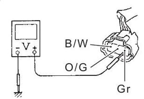
Self-Diagnostic Code “2 – 2” Air Intake System
Wiring Diagram
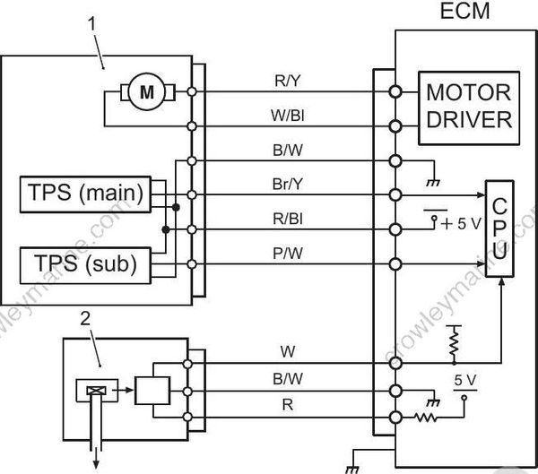
- Electronic throttle body
- MAP sensor
Troubleshooting
Step 1
Remove the fuel hose guard.
With the main switch “OFF”, disconnect the electronic throttle body connector.
With the main switch “ON”, check the voltage at the “R/Bl” wire terminal of electronic throttle body connector.
Is the voltage approx. 4 – 5 V?
Yes Go to step 2.
No • “R/Bl” wire open, “R/Bl” wire shorted to ground circuit or poor wire connection.
• If the wiring and connection is OK, substitute a known-good ECM and recheck.
Step 2
- Check the TPS output voltage change. Refer to “TPS Inspection” in Section 1C (Page 1C31).
Is it in good condition?
Yes Go to step 3.
No • Faulty TPS.
• “R/Bl” wire shorted to “Br/Y” or “P/W” wire, “B/W” wire open, poor “B/W” wire
connection, poor “Br/Y” or “P/W” wire connection, “Br/Y” or “P/W” wire open or poor TPS connection.
• If the wiring and connection is OK, intermittent trouble or a faulty ECM may be the cause.
Step 3
- Check the MAP sensor, electronic throttle control and intake manifold (system) for air leakage.
Is the result OK?
Yes Intermittent trouble or faulty ECM. Substitute a known-good ECM and recheck.
No Faulty air intake system.
For step 1
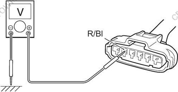
Self-Diagnostic Code “3 – 2” MAP Sensor 2
Wiring Diagram
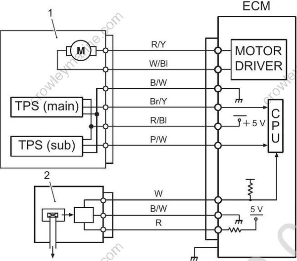
- Electronic throttle body
- MAP sensor
Troubleshooting
Step 1
Remove the fuel hose guard.
With the main switch “OFF”, disconnect the MAP sensor connector.
With the main switch “ON”, check the voltage at the “R” wire terminal of the MAP sensor connector.
Is the voltage approx. 4 – 5 V?
Yes Go to step 2.
No • “R” wire open, “R” wire shorted to ground circuit or poor wire connection.
• If the wiring and connection is OK, substitute a known-good ECM and recheck.
Step 2
- Check the MAP sensor output voltage change.
Refer to “MAP Sensor Output Voltage Inspection” in Section 1C (Page 1C-16).
Is it in good condition?
Yes Go to step 3.
No Faulty MAP sensor.
Step 3
With the main switch “OFF”, disconnect the electronic throttle body connector.
With the main switch “ON”, check the voltage at the “R/Bl” wire terminal of the electronic throttle body connector.
Is the voltage approx. 4 – 5 V?
Yes Go to step 4.
No • “R/Bl” wire open, “R/Bl” wire shorted to ground circuit or poor wire connection.
• If the wiring and connection is OK, substitute a known-good ECM and recheck.
Step 4
- Check the TPS output voltage change.
Refer to “TPS Inspection” in Section 1C (Page 1C-31).
Is it in good condition?
Yes Intermittent trouble, substitute a known-good ECM and recheck.
No • Faulty TPS.
• “R/Bl” wire shorted to “Br/Y” or “P/W” wire, “B/W” wire open, poor “B/W” wire connection, poor “Br/Y”or “P/W” wire connection, “Br/Y” or “P/W” wire open or poor TPS connection.
• If the wiring and connection is OK, intermittent trouble or a faulty ECM may be the cause.
For step 1
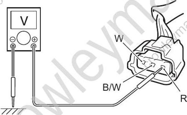
For step 3
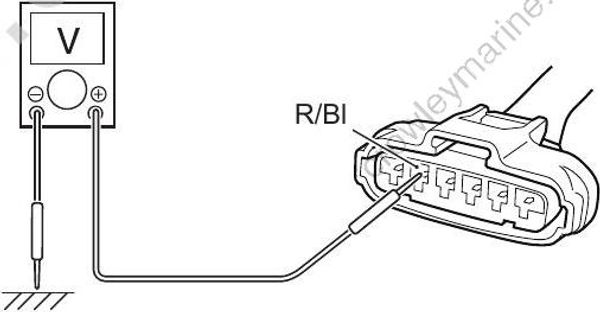
Self-Diagnostic Code “3 – 3” Neutral Switch
Wiring Diagram
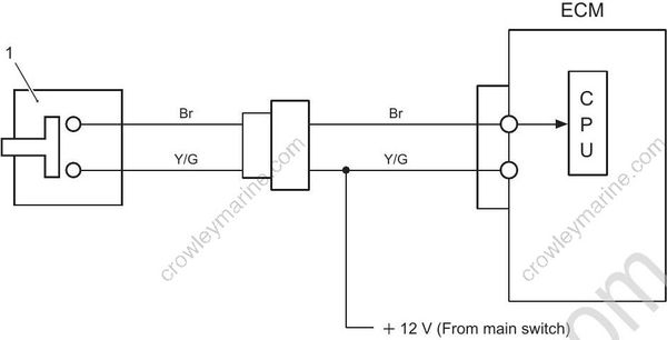
- Neutral switch
Troubleshooting
Step 1
Remove the lower side covers and front panel.
With the main switch “OFF”, disconnect the neutral switch connector.
With the main switch “ON”, check the voltage at the “Y/G” wire terminal of the neutral switch connector.
Is the voltage 12 V or more?
Yes Go to step 2.
No * “Y/G” wire shorted to “Br” wire or ground circuit.
- If the wiring and connection is OK, substitute a known-good ECM and recheck.
Step 2
- Check the neutral switch.
Refer to “Neutral Switch Inspection” in Section 1I (Page 1I-18).
Is it in good condition?
Yes * Poor neutral switch connection, intermittent trouble or a faulty ECM.
Shift position sensor lever damage.
No Faulty neutral switch.*For step 1**
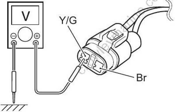
Self-Diagnostic Code “5 – 1” VVT Advance
Wiring Diagram
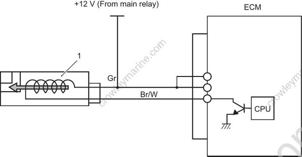
- OCV
Troubleshooting
Step 1
- With the main switch “OFF”, disconnect the connector from OCV. 2) Check the voltage at “Gr” wire terminal with the main switch “ON”.
Is the voltage 12 V (battery voltage)?
Yes Go to step 2.
No * Power circuit open.
- “Gr” wire shorted to “Br/W” wire or ground circuit.
- If the wiring and connection is OK, substitute known-good ECM and recheck.
Step 2
- Inspect OCV and OCV gasket filter condition.
Refer to “OCV (Oil Control Valve) Inspection” in Section 1C (Page 1C-21).
Is the result OK?
Yes * Poor OCV connection, intermittent trouble or a faulty ECM.
- Clogged OCV oil passage.
No Faulty OCV.
Self-Diagnostic Code “5 – 3” Oil Pressure Switch
Wiring Diagram
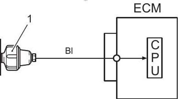
- Oil pressure switch
Troubleshooting
Step 1
With the main switch “OFF”, remove the oil pressure switch wire.
With the main switch “ON”, check the voltage between the oil pressure switch wire terminal and body ground.
Is the voltage approx. 5 V?
Yes Go to step 2.
No * Oil pressure switch wire open or poor connection.
- If wire and connection are OK, substitute a known-good ECM and recheck.
Step 2
- Check the oil pressure switch operation.
Refer to “Oil Pressure Switch Inspection” in Section 1E (Page 1E-8).
Is it in good condition?
Yes Poor oil pressure switch wire connection, intermittent trouble or a faulty ECM may be the cause.
No Faulty oil pressure switch.
For step 1
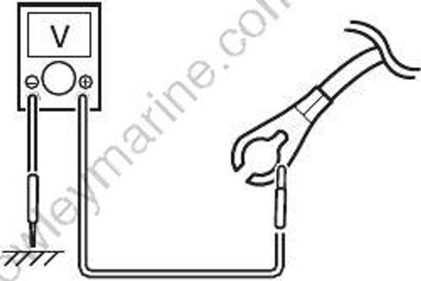
Self-Diagnostic Code “6 – 1” OCV (Oil Control Valve)
Wiring Diagram
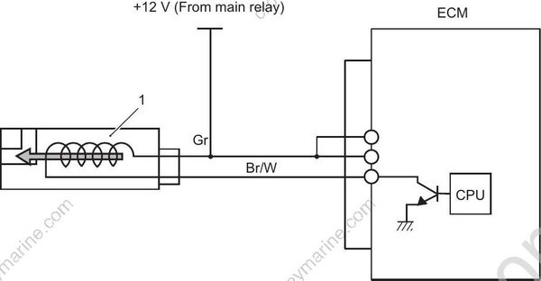
- OCV
Troubleshooting
Step 1
- Inspect OCV.
Refer to “OCV (Oil Control Valve) Inspection” in Section 1D (Page 1D-18).
Is the result OK?
Yes Poor OCV wire connection, intermittent trouble or a faulty ECM may be the cause.
No Faulty OCV.
Self-Diagnostic Code “5 – 4” Knock Sensor
Wiring Diagram
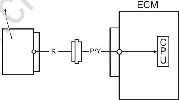
- Knock sensor
Troubleshooting
Step 1
- Inspect knock sensor.
Refer to “Knock Sensor Inspection” in Section 1C (Page 1C-20).
Is it in good condition?
Yes Poor knock sensor connection, intermittent trouble or a faulty ECM may be the cause.
No Faulty knock sensor.
Self-Diagnostic Code “3 – 6” O2 Sensor
Wiring Diagram
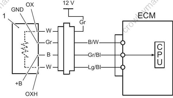
- O2 sensor
Troubleshooting
Step 1
With the main switch “OFF”, disconnect the O2 sensor connector.
Check continuity between Gr/Bl terminal of O2 sensor connector and ground, also between Gr/Bl and B/W terminals of O2 sensor connector. Make sure there are not continuity.
Disconnect ECM connectors. Refer to “ECM Removal and Installation” (Page
1A-85).Check continuity between Gr/Bl terminal of O2 sensor connector (harness side) and No.18 terminal of ECM connector (harness side), also between B/W terminal and No.6 terminal. Make sure there are continuity. Are they in good condition?
Yes Go to step 2.
No Gr/Bl wire shorted, or Gr/Bl or B/W wire open
Step 2
- Check the O2 sensor output voltage. Refer to “O2 Sensor Output Voltage Inspection” in Section 1C (Page 1C-18).
Is each voltage OK?
Yes Poor O2 sensor connection, intermittent trouble or a faulty ECM may be the cause.
No Faulty O2 sensor.
For step 1
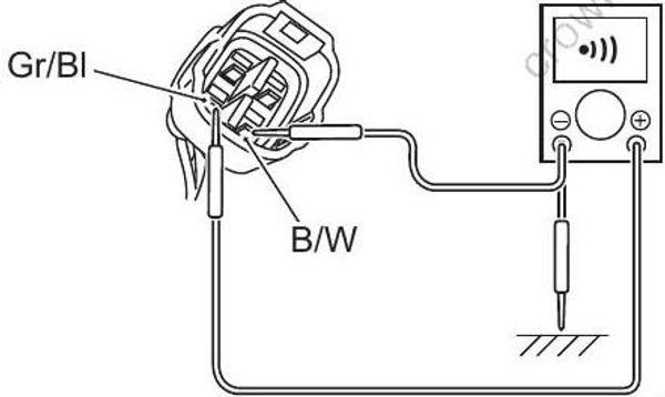
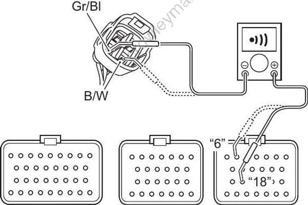
Self-Diagnostic Code “6 – 3” O2 Sensor Heater
Wiring Diagram
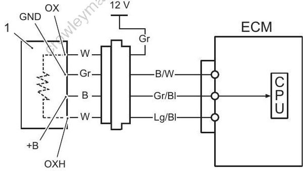
- O2 sensor
Temperature of the sensor affects resistance value largely. Make sure that the sensor heater is in atmospheric temperature.
Troubleshooting
Step 1
With the main switch “OFF”, disconnect the O2 sensor connector.
Measure the resistance between W terminals of O2 sensor.
Is the resistance 5.5 – 8.5 Ω at 20 °C (68 °F)?
Yes Go to Step 2.
No Faulty O2 sensor.
Step 2
- Check the O2 sensor heater voltage.
Refer to “O2 Sensor Heater Inspection” in Section 1C (Page 1C-19).
Is the voltage OK?
Yes
- Gr or Lg/Bl wire open or shorted to ground, or poor No.85 terminal connection.
- If wires and their connection are OK, intermittent trouble or a faulty ECM may be the cause.
No
- Gr or Lg/Bl wire shorted or open.
- Poor connection on O2 sensor or ECM connector.
For step 1
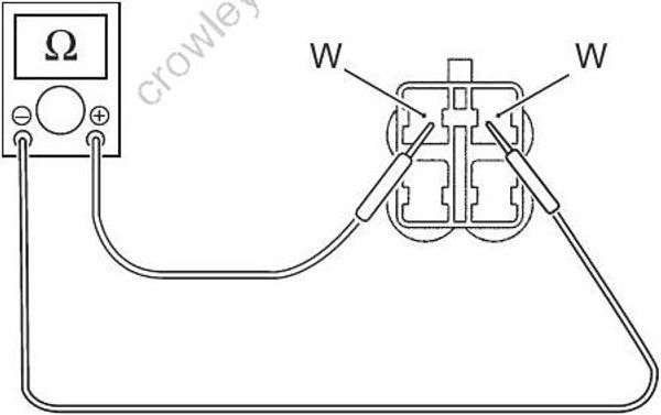
Self-Diagnostic Code “7 – 1” ETV (Electronic Throttle Valve) ECM
Wiring Diagram
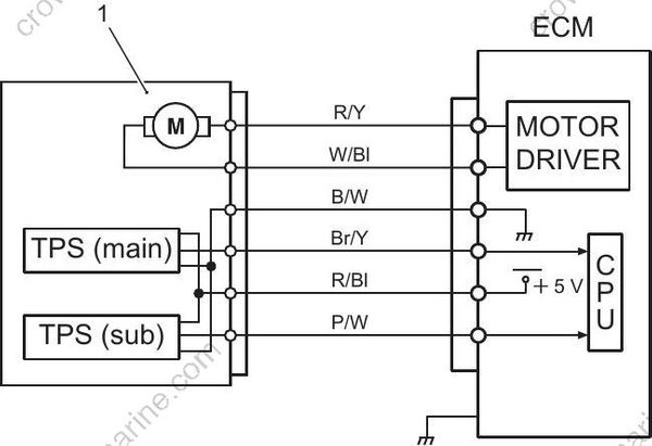
- Electronic throttle body
Troubleshooting
Step 1
Is the electronic throttle body installed properly and the wire harness connected securely?
Yes Go to step 2.
No Correct.
Step 2
- If the wiring and connection is OK, substitute a known-good ECM and check ETV operation. Refer to “Electronic Throttle Body Assembly Operation Check” (Page 1A-84).
Is the result OK?
Yes Faulty ECM.
No Faulty wire connection.
If the wiring and connection is OK, intermittent trouble or a faulty electronic throttle body may be the cause.
Self-Diagnostic Code “7 – 2” ETV (Electronic Throttle Valve) Motor
Wiring Diagram
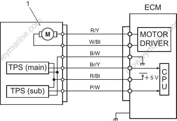
- Electronic throttle body
Troubleshooting
Step 1
- Inspect ETV motor resistance. Refer to “ETV Motor Relay Inspection” in Section 1C (Page 1C-34).
Is the result OK?
Yes Go to Step 2.
No Faulty ETV motor.
Step 2
- Inspect ETV motor relay. Refer to “ETV Motor Relay Inspection” in Section 1C (Page 1C-34).
Is the result OK?
Yes Go to Step 3.
No Faulty ETV motor relay.
Step 3
- Inspect ETV motor / motor relay circuit. Refer to “ETV Motor / Motor Relay Circuit Inspection” in Section 1C (Page 1C-33).
Is the result OK?
Yes Substitute a known-good ECM and recheck.
No Poor system wire connection, intermittent trouble or a faulty ECM.
Self-Diagnostic Code “7 – 3” ETV (Electronic Throttle Valve)
Wiring Diagram
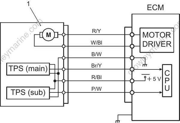
- Electronic throttle body
Troubleshooting
Step 1
- With the main switch “OFF”, inspect the electronic throttle valve.
Refer to “Electronic Throttle Body Inspection” in Section 1D (Page 1D-14).
Is the result OK?
Yes Go to Step 2.
No Faulty electronic throttle body assembly.
Step 2
- With the main switch “ON”, inspect ETV operation.
Refer to “Electronic Throttle Body Assembly Operation Check” (Page 1A-84).
Is the result OK?
Yes Substitute a known-good ECM and recheck.
No Poor system wire connection, intermittent trouble or a faulty electronic throttle body.
Self-Diagnostic Code “7 – 4” Sub BCM (Boat Control Module)
Wiring Diagram
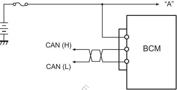
“A”: To main switch
Troubleshooting
Step 1
- With the main switch “ON”, measure the BCM No.51 terminal voltage. Refer to “Inspection of the BCM and Its Circuit” (Page 1A-75).
Is the result OK?
Yes Go to Step 2.
No * Poor BCM power source wire connection.
- Faulty BCM power circuit.
Step 2
- Measure the BCM No.27 and No.28 terminal voltage. Refer to “Inspection of the BCM and Its Circuit” (Page 1A-75).
Is the result OK?
Yes Faulty sub BCM.
No * Faulty wire connection.
- If the wiring and connection is OK, intermittent trouble or a faulty BCM may be the cause.
Self-Diagnostic Code “7 – 5” DBW (Drive By Wire) System
Wiring Diagram
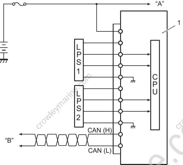
- BCM
“A”: To main switch
“B” To ECM
Troubleshooting
Step 1
- With the main switch “ON”, measure the BCM No.51 terminal voltage. Refer to “Inspection of the BCM and Its Circuit” (Page 1A-75).
Is the result OK?
Yes Go to Step 2.
No * Poor BCM power source wire connection.
- If the wiring and connection is OK, intermittent trouble or a faulty BCM may be the cause.
Step 2
- Select 1st station.
Inspect 1st LPS output voltage change.
Refer to “Lever Position Sensor Inspection” in Section 1C (Page 1C-32).
Is the result OK?
Yes Go to Step 3.
No * Faulty LPS.
- Poor LPS wire connection.
- If the wiring and connection is OK, intermittent trouble or a faulty BCM may be the cause.
Step 3
- Select 2nd station.
Inspect 2nd LPS output voltage change. Refer to “Lever Position Sensor Inspection” in Section 1C (Page 1C 32).
Is the result OK?
Yes Go to Step 4.
No * Faulty LPS.
- Poor LPS wire connection.
- If the wiring and connection is OK, intermittent trouble or a faulty BCM may be the cause.
Step 4
- Measure the ECM No.7 and No.13 terminal voltage.
Refer to “Inspection of the ECM and Its Circuit” (Page 1A-71).
Is the result OK?
Yes Go to Step 5.
No * Faulty CAN communication line.
- Poor wire connection.
- If the wiring and connection is OK, intermittent trouble or a faulty ECM may be the cause.
Step 5
- Measure the BCM No.27 and No.28 terminal voltage.
Refer to “Inspection of the BCM and Its Circuit” (Page 1A-75).
Is the result OK?
Yes Intermittent trouble, substitute a known-good BCM/ECM and recheck.
No * Faulty CAN communication line.
- Poor wire connection.
- If the wiring and connection is OK, intermittent trouble or a faulty BCM may be the cause.
Self-Diagnostic Code “8 – 1” ESA (Electronic Shift Actuator) ECM
Wiring Diagram
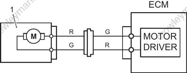
Troubleshooting
Step 1
- Check the electronic shift system operation using ECM that is known to be in good condition. Refer to “ESA Motor / Motor Relay Circuit Inspection” in Section 1C (Page 1C-28).
Is the result OK?
Yes Faulty ECM.
No Faulty wire continuity and/or connection.
Self-Diagnostic Code “8 – 2” ESA (Electronic Shift Actuator) Motor
Wiring Diagram
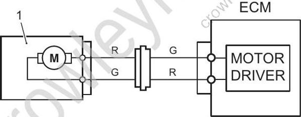
- ESA
Troubleshooting
Step 1
- Check the ESA motor resistance. Refer to “ESA Motor Inspection” in Section 1C
(Page 1C-30).
Is the result OK?
Yes Go to Step 2.
No Faulty ESA motor.
Step 2
- Check ESA motor relay. Refer to “ESA Motor Relay Inspection” in Section
1C (Page 1C-29).
Is the result OK?
Yes Go to Step 3.
No Faulty ESA motor relay
Step 3
- Check the ESA motor / motor relay circuit. Refer to “ESA Motor / Motor Relay Circuit
Inspection” in Section 1C (Page 1C-28).
Is the result OK?
Yes Poor motor wire connection, intermittent trouble or a faulty ESA motor may be the cause.
No • Faulty ECM
• Faulty motor wire connection and/or continuity
Self-Diagnostic Code “8 – 3” ESA (Electronic Shift Actuator)
Wiring Diagram
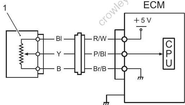
- SPS
Troubleshooting
Step 1
- Check the shift position sensor output voltage. Refer to “Shift Position Sensor Power Source and Output Voltage Inspection” in Section 1C (Page 1C-24).
Is the result OK?
Yes Go to Step 2.
No Faulty shift position sensor.
Step 2
Remove the main relay from fuse box. Remove the clutch link rod from clutch lever.
To check smooth gear engagement, shift the clutch control lever to Forward and Reverse position from Neutral position.
Is the result OK?
Yes
- Faulty ESA
- Faulty shift position sensor wire connection and/or continuity.
- If the wiring and connection is OK, intermittent trouble or a faulty ECM may be the cause.
No Shift link mechanism failure.
Self-Diagnostic Code “4 – 1” Model Distinction Switch
Wiring Diagram
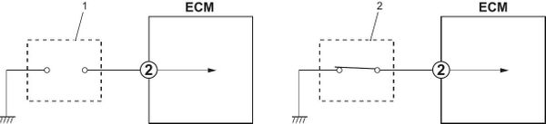
- Regular select connector
- Counter select connector
Troubleshooting
Step 1
Disconnect the ECM connectors from ECM with the main switch “OFF”.
Check the ECM connector for loose or poor contacts.
If OK, then check the continuity between No.2 terminal of ECM connector (harness side) and engine body ground.No.2 terminal continuity
Regular rotation condition: No continuity
Counter rotation condition: Continuity
Is the result OK?
Yes Counter / Regular select connector and its circuit are in good condition.
No
- Faulty counter / regular select connector.
- “O/Y” wire shorted to “B” wire, “O/Y” wire open, poor “O/Y” wire connection, or poor counter / regular select connector connection.
- If the wiring and connection is OK, intermittent trouble or a faulty ECM.
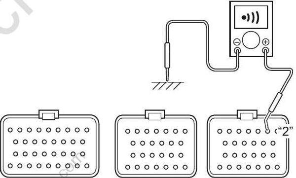
Self-Diagnostic Code “9 – 4” Keyless System Authentication Error
This condition:
ECM detected that its ID code does not correspond with the ID code registered in the keyless control unit.
Correction:
- Change the ECM to correspond with their ID codes.
Self-Diagnostic Code “9 – 5” Keyless System Communication Error
This condition:
The ECM cannot receive CAN communication information from keyless control unit.
Correction:
Check communication such as open circuit on communication wire, poor or loose connections.
Check the CAN communication line output voltage.
Refer to “Inspection of the Keyless Control Unit and Its Circuit” (Page 1A-82).
Self-Diagnostic Code “9 – 6” Keyless System Failure
This condition:
There is an irregularity on the internal circuit of the keyless control unit.
Correction:
Replace the keyless control unit and ECM.
Troubleshooting Without Self-Diagnostic Code
Before troubleshooting, make sure that there is not a self-diagnostic code indication.
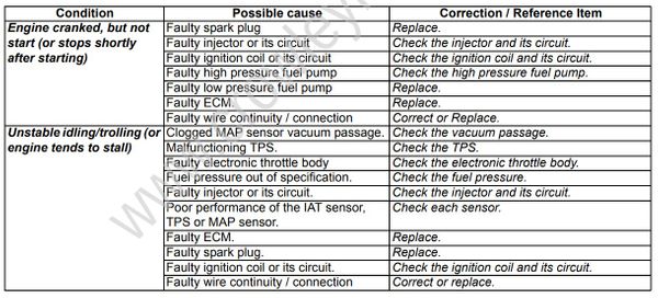
Service Instructions
How to Use the 26-pin and 34-pin Test Cord Set
This test cord is used when checking a circuit for voltage, etc. and is connected between the ECM or BCM and the wiring harness.
To take a measurement, connect the tester probe to the relevant terminal of the test cord.
(A): 09930–89340 (26-pin & 34-pin test cord)
(B): 09930–89850 (26-pin (B) test cord)
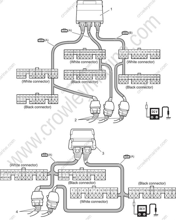
- ECM
- Wire harness
- BCM
- Wire harness
Inspection of the ECM and Its Circuit
If you connect a voltmeter or ohmmeter directly to ECM terminals by removing ECM connector, you can damage the control module. Never connect a voltmeter or an ohmmeter directly to any terminal of ECM by disconnecting control module connector.
Special tool
(A): 09930–89340 (26-pin & 34-pin test cord)
(B): 09930–89850 (26-pin (B) test cord)
09900–25008 (Multi circuit tester set)
Tester knob indication
DC Voltage ( )
Turn main switch OFF.
Connect the 26-pin (A), (B) and 34-pin test cord between ECM and wire harness as shown in figure.
Turn main switch ON.
Connect the tester probe (“–”, Black) to body ground, and measure voltage according to the “ECM Circuit Voltage Table” (Page 1A-72).
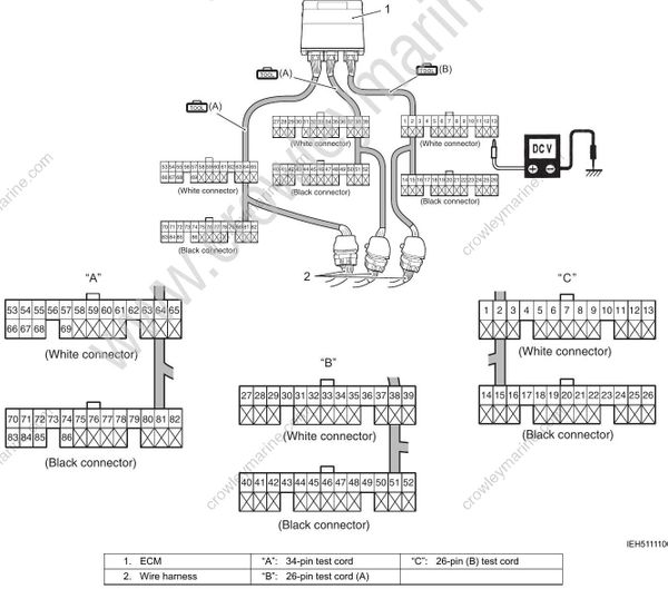
1.ECM
2.Wire harness
“A”:34-pin test cord
“B”:26-pin test cord (A)
“C”:26-pin (B) test cord
ECM Circuit Voltage Table
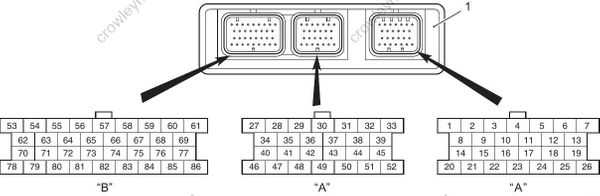
- ECM
“A”: 26-pin connector
“B”: 34-pin connector
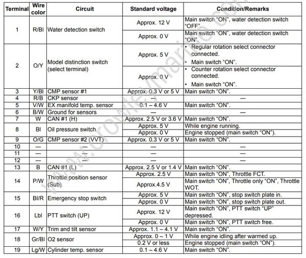
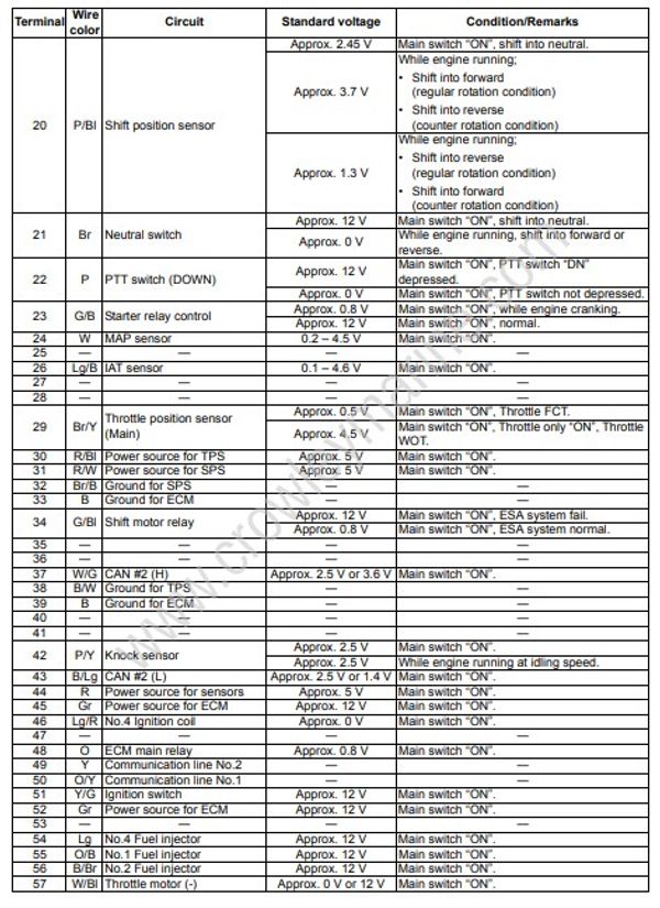
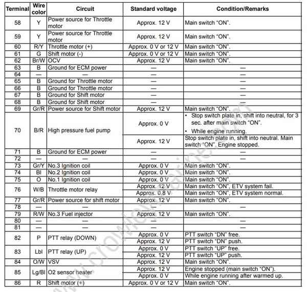
Inspection of the BCM and Its Circuit
If you connect a voltmeter or ohmmeter directly to BCM terminal by removing BCM connector, you can damage the control module. Never connect a voltmeter or an ohmmeter directly to any terminal of BCM by disconnecting control module connector.
Special tool
(A): 09930–89340 (26-pin & 34-pin test cord)
09900–25008 (Multi circuit tester set)
Tester knob indication
DCV ( )
Turn main switch OFF.
Connect the 26-pin (A) and 34-pin test cord between BCM and BCM wire harness assembly as shown in figure.
Turn main switch ON.
Connect the tester probe (“–”, Black) to No.43 terminal (or body ground), and measure voltage according to the “BCM Circuit Voltage Table”.
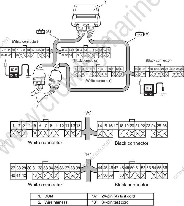
- BCM
- Wire harness
“A”:26-pin (A) test cord
“B”:34-pin test cord
BCM Circuit Voltage Table
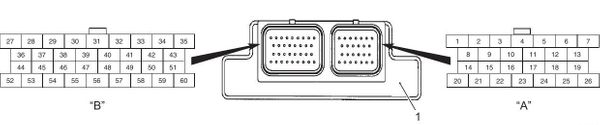
- BCM
“A”: 26-pin connector
“B”: 34-pin connector
For single / twin / triple engine
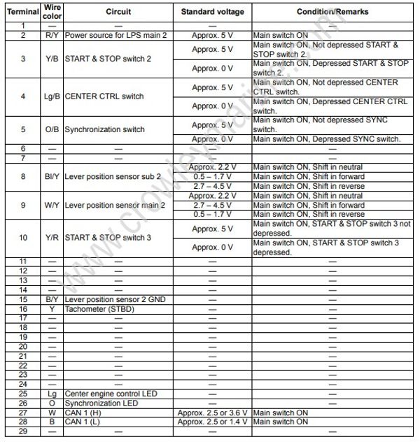
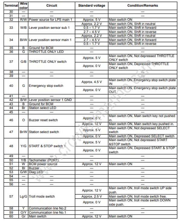
For single / twin / triple engine
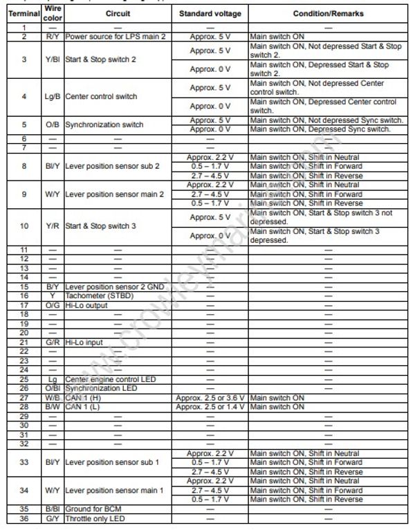
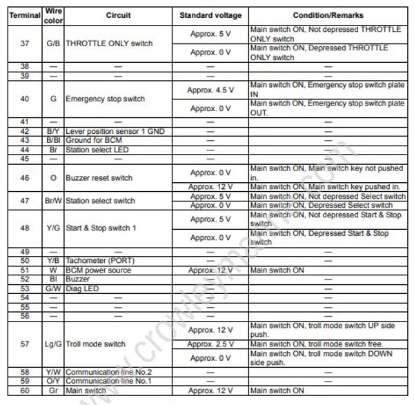
For quadruple engine (STBD engine group)
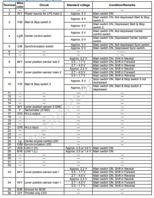
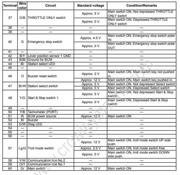
For quadruple engine (PORT engine group)
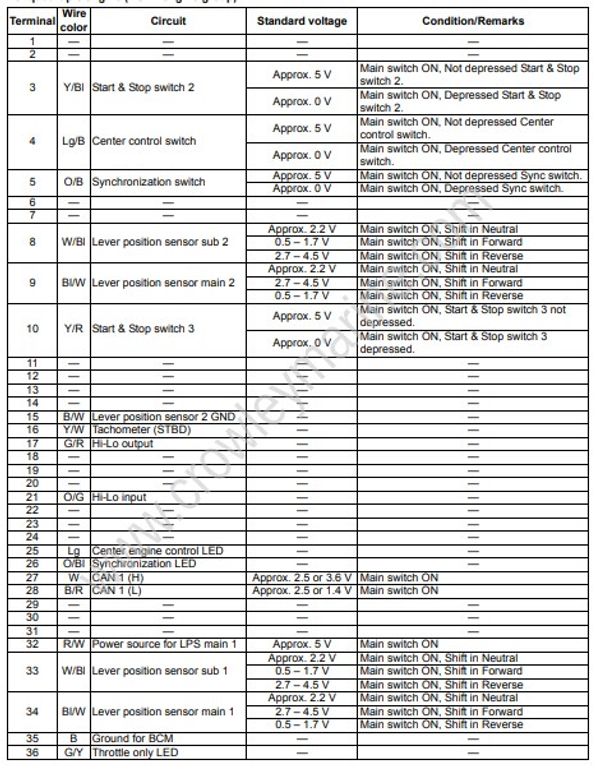
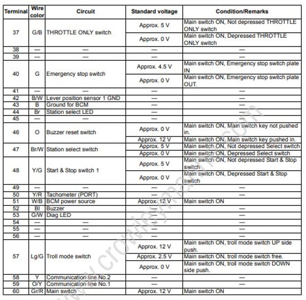
Inspection of the Keyless Control Unit and Its Circuit
If you connect a voltmeter or ohmmeter directly to keyless control unit terminals by removing keyless control unit connector, you can damage the control unit. Never connect a voltmeter or an ohmmeter directly to any terminal of keyless control unit by disconnecting control unit connector.
Special tool
(A): 09930–89290 (18 pin & 34 pin test cord)
09900–25008 (Multi circuit tester set)
Tester knob indication
DCV ( )
In this inspection, the 34 pin test cord in the test cord set is not required.
Turn the main switch “OFF”.
Connect the 18-pin test cord between the keyless control unit and wire harness as shown in figure.
Turn the main switch “ON”.
Connect the tester probe (“–”, Black) to No.14 terminal (or to body ground), and measure the voltage according to the “Keyless Control Unit Circuit Voltage Table” (Page 1A-83).
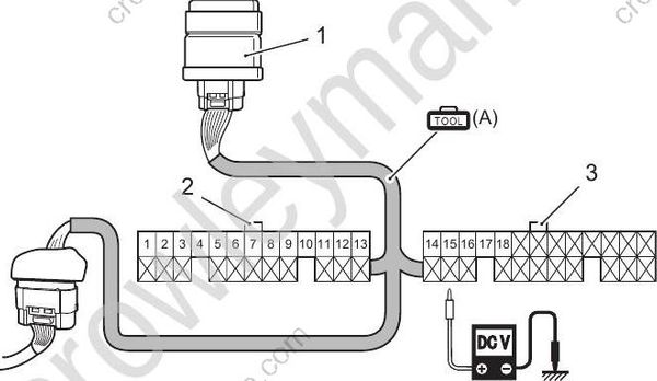
- Keyless control unit
- White connector
- Black connector
Keyless Control Unit Circuit Voltage Table
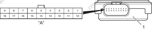
- Keyless control unit
“A”: 18-pin connector
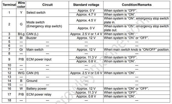
Electronic Throttle Body Assembly Operation Check
Failure to take proper precautions when handling the electronic throttle body assembly, may lead to malfunction of the electronic throttle body assembly or damage to its components.
• Do not disassemble the electronic throttle body assembly.
• Do not drop or otherwise expose the electronic throttle body assembly to large shock. Any electronic throttle body assembly that has received large shock should be replaced.
• Keep the electronic throttle body housing and/or throttle valve free of dust, metallic particles or other foreign materials.
• Do not apply undue forces to the throttle valve when checking operation of the throttle valve or performance of the throttle position sensor; otherwise the plastic gears in the throttle valve actuator will be damage.
Remove the ring gear cover and air intake silencer case.
Refer to “Air Intake Silencer Case Removal and Installation” in Section 1D (Page 1D-2).Turn the main switch “ON”.
Confirm the select switch LED lights.
If not, depress the “SELECT” button on switch panel.Depress the “THROTTLE ONLY” button.
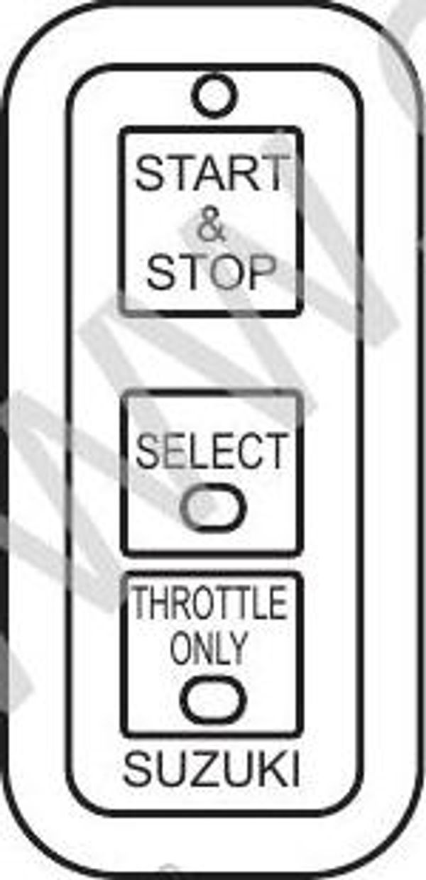
Move remote control lever gradually and check that throttle valve moves smoothly until it opens fully.
Return remote control lever in step 5 and check that throttle valve moves back to completely closed position.
If check result is satisfactory, electronic throttle body system is in good condition.
If check result is not satisfactory, proceed to next step.
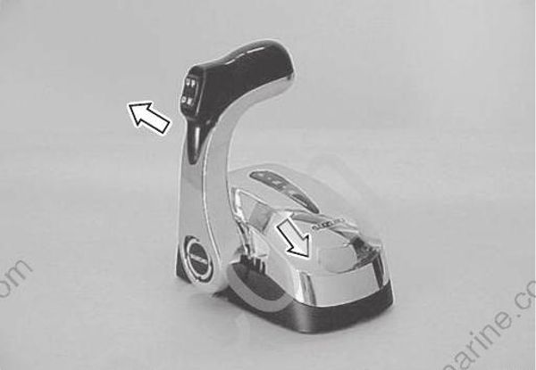
- Perform “Lever Position sensor assembly Inspection”, “Throttle Actuator (Motor) Check” and “Throttle Position Sensor Performance Check”. If check results are not satisfactory, replace electronic throttle body assembly.
If check results are satisfactory, wire circuit and/or ECM, BCM are faulty.
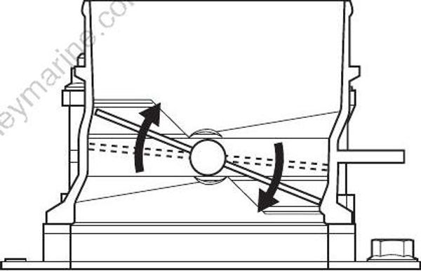
ECM Main Relay Inspection
Inspect the ECM main relay using the following procedures:
Turn the main switch “OFF”.
Disconnect the ECM main relay (1) from the fuse box.
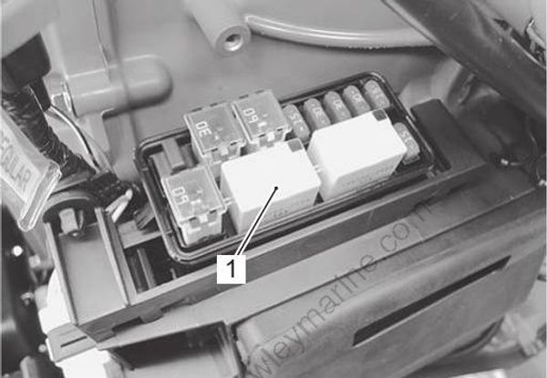
- ECM main relay
Check continuity between terminal (2) and (3) each time 12 V power supply is applied to terminal (4) and (5).
Connect the positive (+) lead to terminal (5), and negative (–) lead to terminal (4).If the 12 V power supply wire is connected to wrong terminal or touched to each other, the power supply wire, tester may be damaged. Be careful not to touch 12 V power supply wires to each other or with other terminals.
Special tool
(A): 09900–25008 (Multi circuit tester set)
Tester knob indication
Continuity ( )
ECM main relay function
| Continuity | |
|---|---|
| 12 V power applied | Yes |
| 12 V power not applied | No |
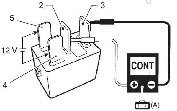
Measure the resistance between relay terminals (4) and (5).
If out of specification, replace ECM main relay.Tester knob indication
Resistance (Ω)
ECM main relay solenoid coil resistance
Standard: 145 – 190 Ω
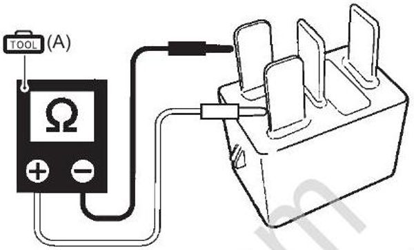
ECM Removal and Installation
Removal
Turn the main switch “OFF”.
Disconnect lead wire connectors (1) from ECM, then remove ECM (2).
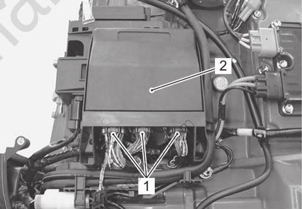
Installation
Installation is reverse order of removal.
Switch Panel Inspection
Single Switch Panel
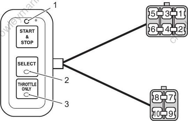
- Red LED
- SELECT LED
- THROTTLE ONLY LED
- Check continuity/infinity between each terminal of the switch by operating them.
Special tool
09900–25008 (Multi circuit tester set)
Tester knob indication
Continuity ( )
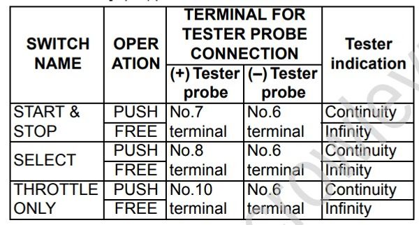
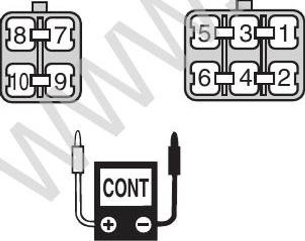
Replace the switch panel if the above test shows out of specification.
- Check if each lamp lights when connecting battery to the terminal.
Use 4.5 V power source (3 new 1.5 V batteries in series) for test.
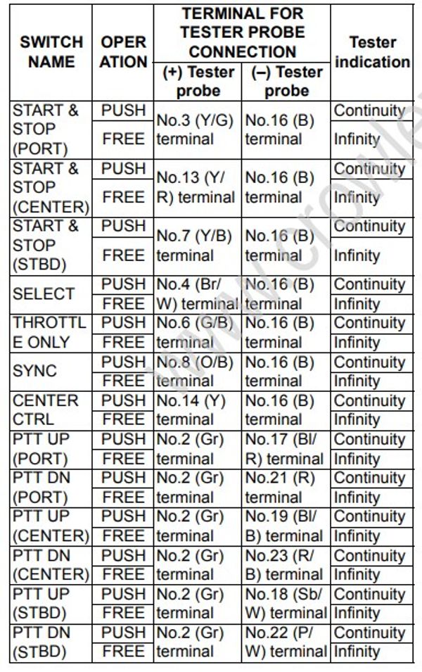
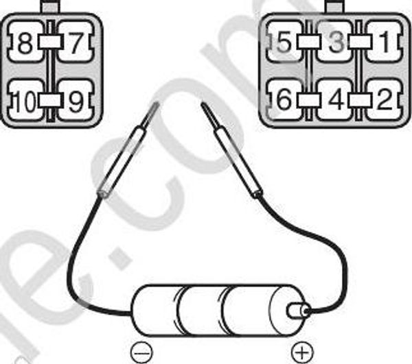
Replace the switch panel if the above test shows out of specification.
Triple Switch Panel / Dual Switch Panel
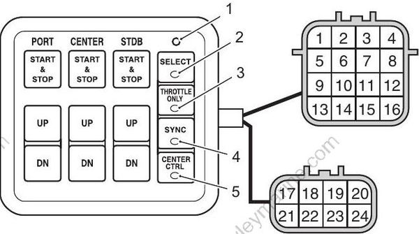
1.Red LED
2.SELECT LED
3.THROTTLE ONLY LED
4.SYNC LED
5.CENTER CTRL LED
- Check continuity/infinity between each terminal of the switch by operating them.
Special tool
09900–25008 (Multi circuit tester set)
Tester knob indication
Continuity ( )
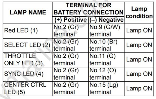
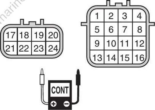
Replace the switch panel if the above test shows out of specification.
- Check if each lamp lights when connecting battery to the terminal.
Use 4.5 V power source (3 new 1.5 V batteries in series) for test.
Image 16
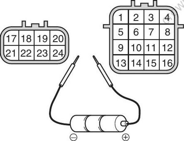
Replace the switch panel if the above test shows out of specification.
Key fob Battery Replacement
- Insert a flat-blade screwdriver in the slot of the key fob, and then pry off the lower case (1). Note the position of O-ring (2).
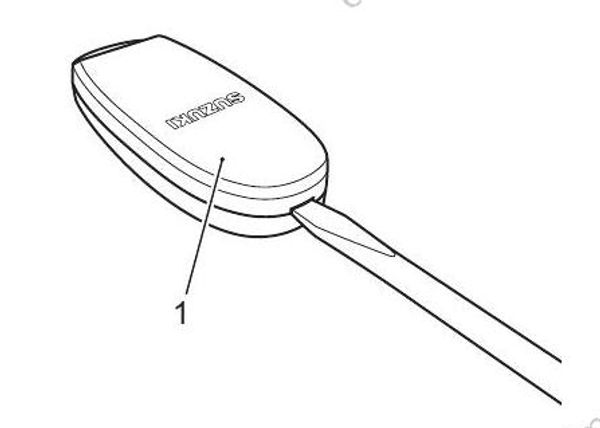
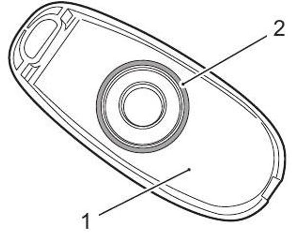
- Remove the battery (3) using a flat-blade screwdriver as shown figure.
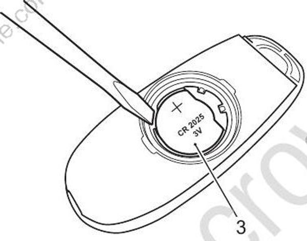
Replace the battery (3) so its (+) terminal faces the lower case side as shown in the illustration.
Lithium disc battery type:
CR2025 or equivalent.
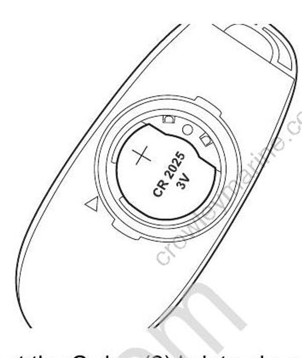
- Confirm that the O-ring (2) is into place on the lower case.
Reinstall the lower case (1), and then fit lower case securely.
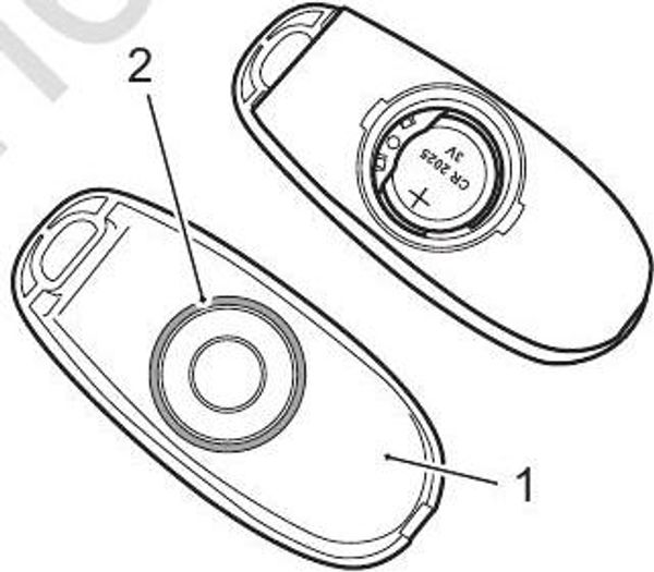
Dispose of the used battery properly according to applicable rules or regulations. Do not dispose of lithium batteries with ordinary household trash.
ECM Power Relay Inspection
Inspect the ECM power relay using the following procedures:
Turn the keyless start system “OFF”.
Disconnect the ECM power relay (1) from the keyless wiring.
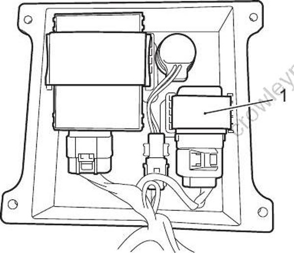
- Check continuity between terminal (2) and (3) each time 12 V power supply is applied to terminal (4) and (5).
Connect the positive (+) lead to terminal (5), and negative (–) lead to terminal (4).
If the 12 V power supply wire is connected to wrong terminal or touched to each other, the power supply wire, tester may be damaged.
Be careful not to touch 12 V power supply wires to each other or with other terminals.
Diodes are used inside the power relay. Failure to correctly supply the battery voltage will result in power relay damage.
Be careful not to short-circuit the positive (+) and negative (–) cable, and connect them only to the correct terminal.
Special tool
09900–25008 (Multi circuit tester set)
Tester knob indication
Continuity
ECM power relay function
| Continuity | |
|---|---|
| 12 V power applied | Yes |
| 12 V power not applied | No |
If out of specification, replace ECM main relay.
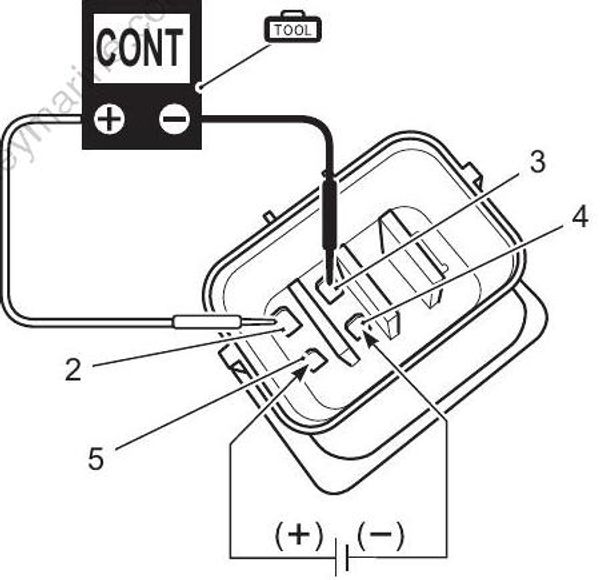
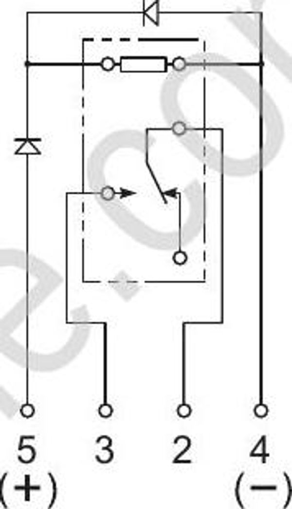
Registering The First Key-Fob ID Code
ID codes of individual key-fobs must be registered to enable the keyless start system:
To register the ID code of the first key-fob, do the following:
Complete the system wiring.
Connect the battery cable and sub battery cable to the battery.
Make sure the key-fob and the keyless control unit are within communication range (1 meter (39.3 in.) or less).
Turn the main switch knob from neutral to “ON & OFF”, then release the knob.
The red LED on the key fob lights up; within 10 seconds, briefly press the key fob button.
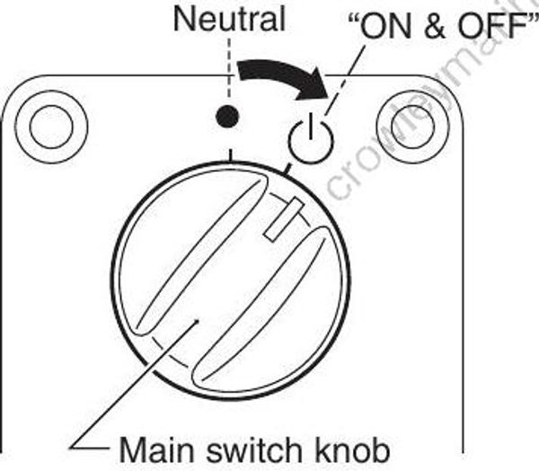
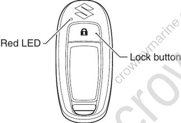
If the buzzer emits five (5) short sounds when the main switch knob is turned from neutral to “ON & OFF” position, the key fob function may be locked. Press the lock button on the key-fob for more than one second to unlock the key fob function. Then perform step 4 again.
When the initial registration is successful, the buzzer emits one (1) short sound, followed by one (1) long sound, and the key fob’s red LED turns off.
• If the ID code registration is not successfully completed, the buzzer emits five (5) short sounds.
• If the registration is not successful, wait for about one minute, then perform step 4 again.To confirm the key-fob registration was successful:
a) Turn and release the main switch knob from “Neutral” to “ON & OFF”.
b) The buzzer emits two (2) short beeps and the green LED in the “SELECT” switch of the control panel turns on.
At this time, the keyless control unit and the ECM become a pair.
For multiple engine applications, the instance setting must be completed before this first key-on action.

Unpairing an ECM from the Keyless Start System
When the outboard motor is resold, removed and started in a test tank, or if it is necessary to use the ECM on another engine, the ECM must be unpaired with the keyless control unit by erasing the ID code in the ECM. Do the following to erase the ID code:
The key-fob ID code registered in the keyless control unit cannot be erased from the keyless control unit.
Make sure the key-fob and the keyless control unit are within communication range.
Turn the main switch knob from “neutral” to “ON & OFF” position, then release the knob.
Confirm that the keyless start system has been turned ON.
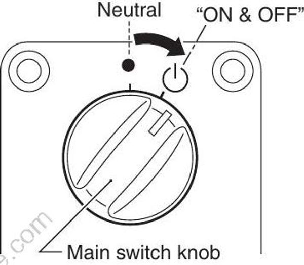
- Connect the black lead wire and the yellow lead wire in the keyless control harness.
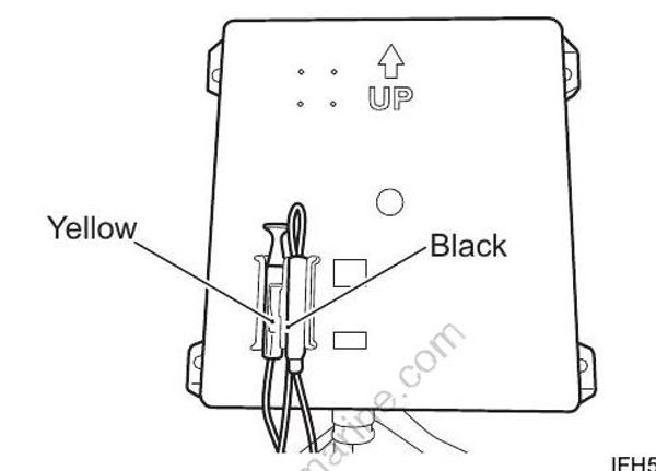
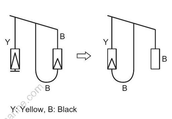
Y: Yellow, B: Black
- The buzzer starts sounding in the following patterns: Four (4) long sounds, followed by:
● Two (2) short sounds emitted four (4) times
● Three (3) short sounds emitted four (4) times
● Four (4) short sounds emitted four (4) times
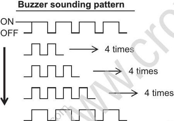
Immediately remove the lock plate from the emergency stop switch, then reinstall it.
If the unpairing is unsuccessful, the buzzer will continuously emit short beeps until the black lead wires are reconnected.
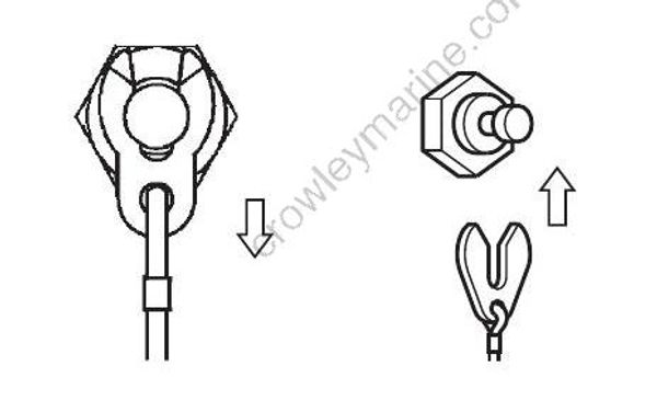
Disconnect the black wire lead from the yellow wire lead, and then reconnect the two (2) black wire leads.
The buzzer sounds when unpairing is completed successfully.
The LED on the “SELECT” switch goes OFF.
Remove the battery cable from the battery.
After unpairing an ECM from the keyless start system, do not turn the main switch knob to “ON & OFF” position.
If the switch is turned, the ID code cross- check will be performed again between the keyless control unit and ECM.