General Description
Electric Starter System Description
The starting circuit consists of the battery, starter motor, main switch, “START & STOP" switch, neutral switch, BCM, ECM and related electrical wiring.
These components are connected electrically as shown in figure below.
In the circuit shown in figure below, the magnetic switch coils are magnetized when the main switch is closed (turn to “ON") and depress the “START & STOP" button.
The resulting plunger and pinion shift lever movement causes the pinion to engage the engine flywheel gear, the magnetic switch main contacts to close, and engine cranking to take place.
When the engine starts, the pinion over—running clutch protects the armature from excessive speed until the switch is opened, at which time the torsion spring causes the pinion to disengage.
Normal key start model
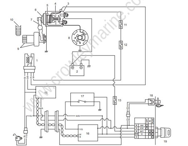
- Starter relay
- Battery
- Magnetic switch
- Pull-in coil
- Hold-in coil
- Plunger
- Shift lever
- Starter motor
- Pinion/over-running clutch
- Ring gear
- 60 A fuse 16. BCM
- Starter relay 30 A fuse 17. START & STOP switch
- 30 A fuse 18. Emergency stop switch
- Neutral switch 19. Main switch
- ECM
- BCM
- START & STOP switch
- Emergency stop switch
- Main switch
Keyless start model
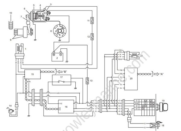
- Starter relay
- Battery
- Magnetic switch
- Pull-in coil
- Hold-in coil
- Plunger
- Shift lever
- Starter motor
- Pinion/over-running clutch
- Ring gear
- 60 A fuse
- Starter relay 30 A fuse
- 30 A fuse
- Neutral switch
- ECM
- BCM
- START & STOP switch
- Emergency stop switch
- Main switch
- Keyless control unit
- ECM power relay
“A”: to ECM
“B”: from keyless control unit
Starter Motor Operation Condition Description
- The starter motor relay will only engage when the main switch is turned to “ON” position and depress the “START & STOP” button if the all of the following conditions are satisfied.
– Lock plate is attached to emergency stop switch.
– Neutral switch is in “ON” position.
– Engine is not already operating.
– When BCM detects that the target shift position is neutral according to the LPS input signal.
– When BCM detects that the actual shift position is neutral according to the SPS (ECM) input signal. - Push the “START & STOP” switch and release it, the starter motor continues to run for 3 seconds until engine starts.
The continuous operating time of the starter motor is set at five seconds.
When this time is exceeded, the starter motor will automatically stop.
If the motor stops, wait about ten seconds for the motor to cool down and try again.
Start-In-Gear Protection System Description
To avoid an accidental movement of the boat at the time of engine starting, the system prohibits the starter motor operation when the shift is “IN”.
At the time of starting, BCM detects the status of each input signal.
When the conditions below are met, pressing “START & STOP” switch causes the start instruction signal to be sent to ECM. Then the starter relay circuit is closed and the starter motor starts to operate.
- When BCM detects that the target shift position is neutral according to the LPS input signal.
- When BCM detects that the actual shift position is neutral according to the SPS (ECM) input signal.
- When ECM and BCM detects emergency stop switch OFF signal.
If “START & STOP” switch is pressed and the start instruction signal from BCM is not inputted to ECM, the starter motor does not operate and ECM does not output the injection drive signal, ignition signal, high pressure fuel pump drive signal to the respective actuators.
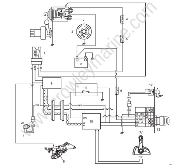
- Starter relay
- Battery
- Starter motor
- 60 A fuse
- Starter relay 30 A fuse
- 30 A fuse
- Neutral switch
- Shift position sensor
- ECM
- BCM
- START & STOP switch
- Emergency stop switch
- Main switch
“A”: Neutral
“B”: LPS signal
The illustration below is for the regular rotation.
When changing regular rotation to counter one, forward position and reverse one become opposite.
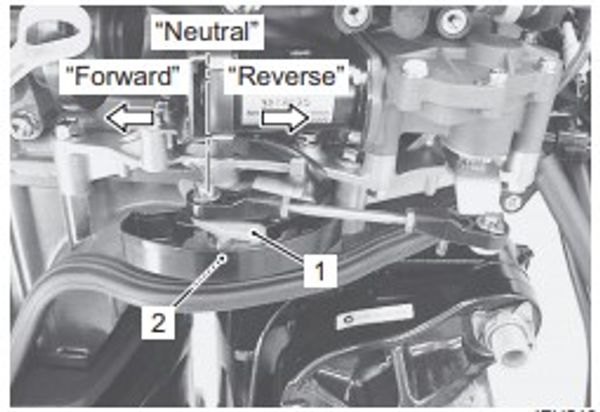
- Clutch lever
- Neutral switch