Component Location
Location of Sensor and Switch
Refer to “Wiring Harness Routing Diagram” in Section 4A (Page 4A-4).
Service Instructions
Resistance Check
Special tool
09900-25008 (Multi circuit tester set)
Tester knob indication
Resistance (Ω)
Make sure main switch is always OFF when measuring resistance.
- Turn main switch OFF.
- Disconnect battery cables from battery.
- Disconnect wire harness connectors from ECM.
- Connect the tester probes to terminal (wire harness side) and measure resistance according to the “Resistance Table” (Page 1C-11).
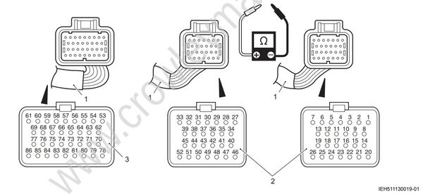
- Wire harness
- 26-pin connector
- 34-pin connector