

ICON COMPONENT SERVICING
To prevent accidental starting while servicing, disconnect the battery cables at the battery.
Electronic Servo Module (ESM)
Disconnect the battery cables at the battery.
Removal
Disconnect the:
• ICON buss cable from ESM
• ESM CANbus harness from EMM
• ESM throttle actuator harness
• ESM shift actuator harness
• ESM power supply harness from solenoid and ground stud
Remove the ESM from studs.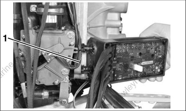
- Retainer mechanism
Installation
Install grommets on ESM. Apply soapy water to grommets and push assembly on to studs.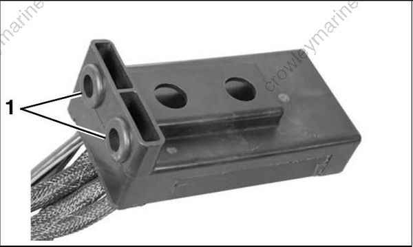
- Grommets
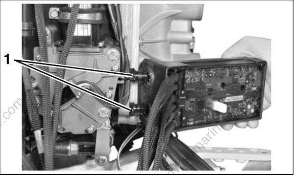
- Studs
Route the CANbus harness from the ESM to the EMM as shown on the starboard side of outboard. Install grommet in notch on the electrical bracket.
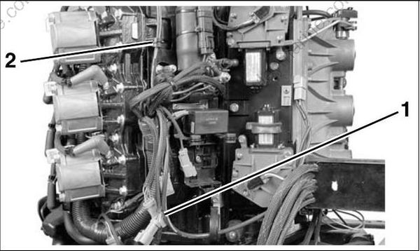
- CANbus harness
- Grommet
Continue harness routing under pressure relief valve hoses to EMM connector. Clip connector to fuel rail. Make sure harness is not strained and does not rub against EMM mounting boss.
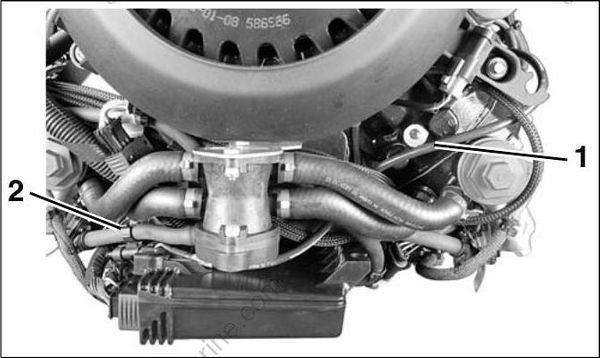
- CANbus harness
- Connector clip
Route ESM to actuator harnesses between actuator plate and engine electrical bracket as shown.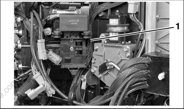
- ESM to actuator harnesses
Route the throttle actuator harness behind and over the oil recirculation hose as shown. Connect to harness from ESM and attach to clip on mounting plate.
Make sure the oil recirculation hose is not pinched during assembly.
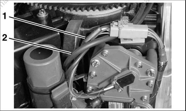
- Harness
- Hose
Secure ESM to throttle actuator harness with tie strap, P/N 320107.
Route ESM to shift actuator harness behind throttle actuator and over throttle actuator harness. Attach to clip on mounting plate.
Install clamp over actuator motor and secure to plate with screw. Tighten screw to a torque of 60 to 84 in. lbs. (7 to 9.5 N·m).
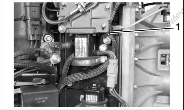
- Throttle harness tie strap
Secure shift actuator harness with tie strap, P/N 317893.
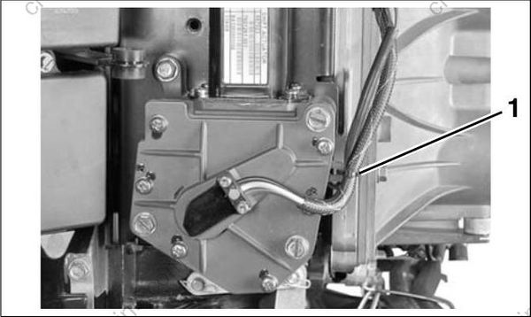
- Shift harness tie strap
Route ESM power supply harness behind trim relay harness. Route negative (–) terminal to battery ground stud and positive (+) terminal to solenoid.
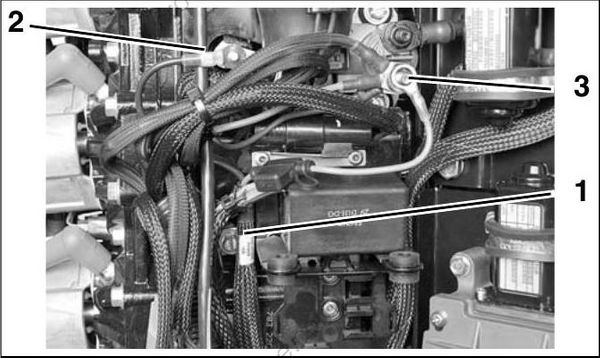
- ESM Power supply harness
- Ground stud
- Solenoid
Install ESM ground, star washer, battery cable, and nut on main ground stud. Tighten to a torque of 60 to 84 in. lbs. (7 to 9.5 N·m).
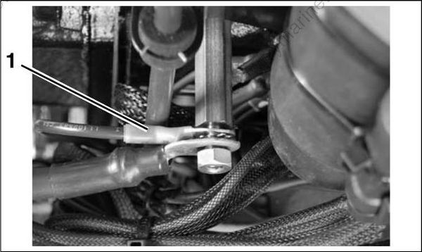
- ESM Ground
Install copper crush washer over ESM positive ring terminal. Then, install star washer, battery cable, and nut. Tighten nut to a torque of 60 to 84 in. lbs (7 to 9.5 N·m).
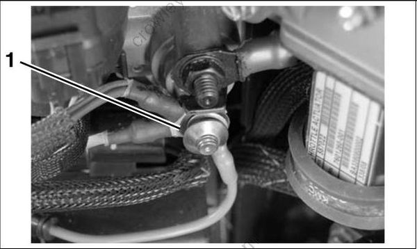
- Copper washer
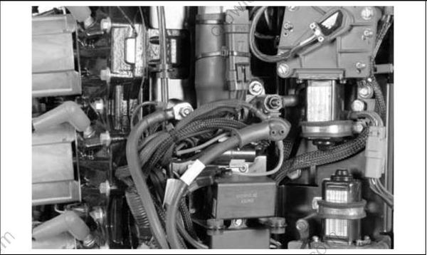
Connect ESM harness to engine harness key switch and trim/tilt connectors.
Secure connectors in bracket as shown and install connector cover.
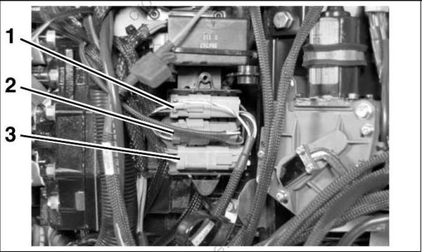
- Key switch connector
- Trim/tilt connector
- SystemCheck connector
Route all ESM harnesses as shown and secure to shift actuator with tie straps, P/N 907833.
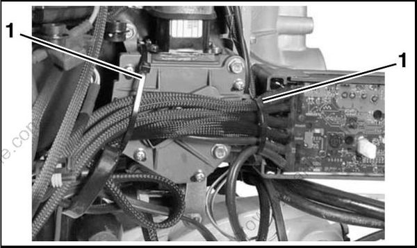
- Large tie straps
Install electrical bracket cover.
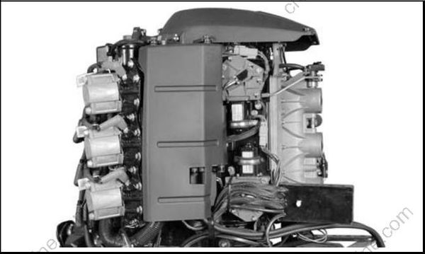
IMPORTANT: Calibrate shift and throttle actuators. Refer to Calibrate Actuator Stroke on p. 209.
Shift Actuator
Removal
Disconnect the battery cables at the battery.
Remove electrical bracket cover.
Observe and note all wire routings before disassembling.
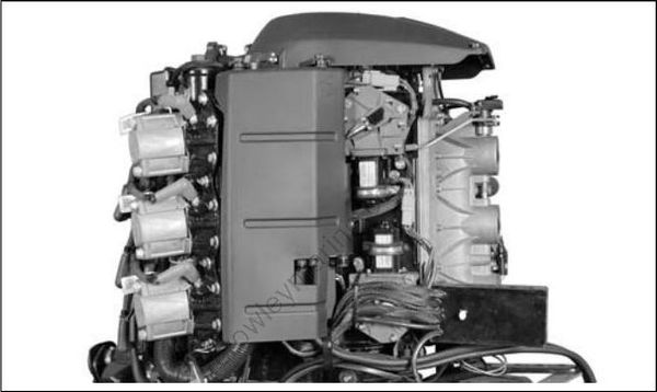
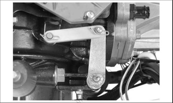
Remove clips and washers from the shift link. Remove the shift link.
Remove the shift actuator connector from the clip on the mounting plate. Disconnect the shift actuator harness.
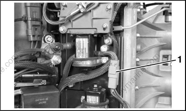
- Shift actuator connector
Remove the clamp retaining screw.
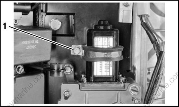
- Clamp retaining screw
Remove the four shift actuator retaining screws.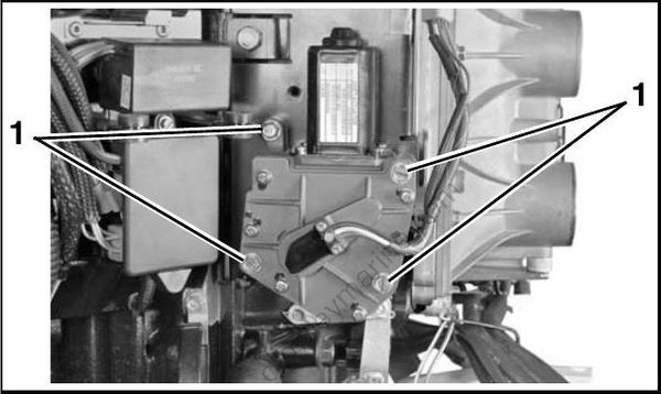
- Shift actuator retaining screws
Installation
Remove old adhesive from clamp retaining screw and shift actuator retaining screws.
Apply Nut Lock to the threads of the screws.
Install shift actuator on mounting plate with three long screws and one short screw. Tighten screws to a torque of 60 to 84 in. lbs. (7 to 9.5 N·m).
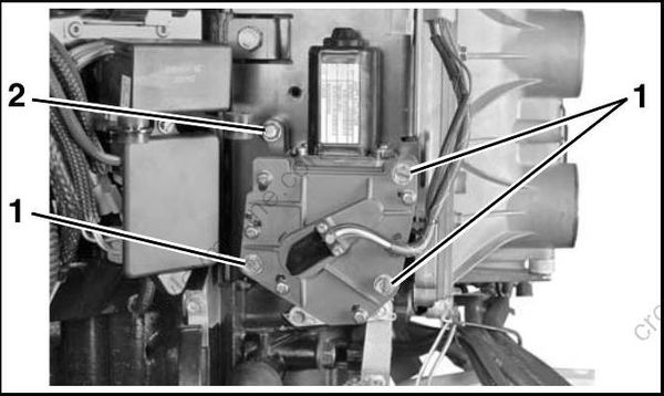
- Long screws
- Short screw
Place clamp over actuator motor. Install and tighten screw to a torque of 60 to 84 in. lbs. (7 to 9.5 N·m).
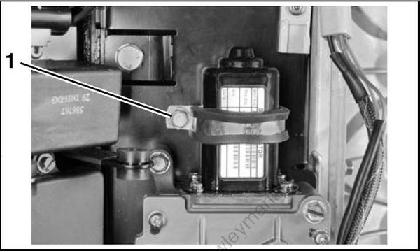
- Clamp retaining screw
Connect the shift actuator harness. Attach to clip on mounting plate.
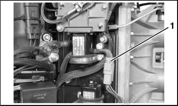
- ESM to shift actuator harness
Secure shift actuator harness with tie strap, P/N 317893.
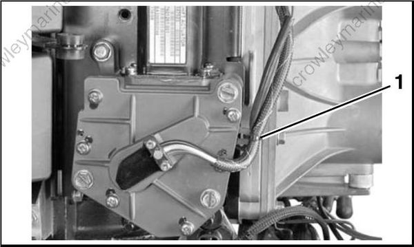
- Shift harness tie strap
Route all ESM harnesses as shown and secure to shift actuator with tie straps, P/N 907833.
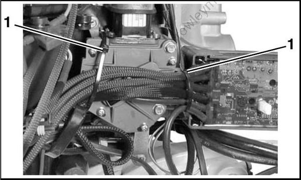
- Large tie straps
IMPORTANT: Do not install shift link until the calibration procedure has been completed. Refer to Calibrate Actuator Stroke on p. 209.
Throttle Actuator
Removal
Disconnect the battery cables at the battery.
Remove the flywheel cover. Remove the electrical bracket cover.
Observe and note all wire routings before disassembling.
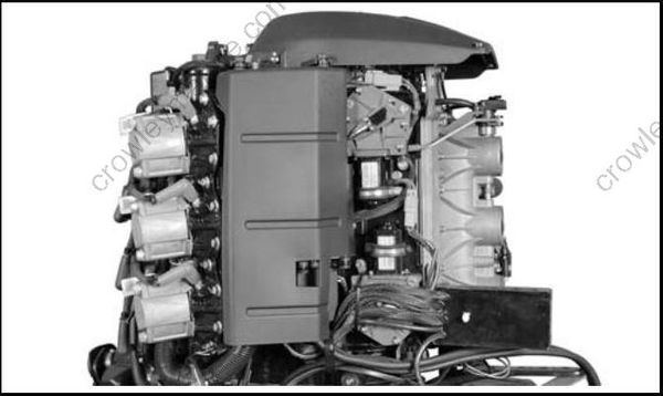
Remove the throttle actuator connector from the clip on the mounting plate. Disconnect the throttle actuator harness.
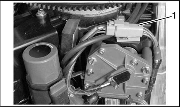
- Throttle actuator connector
Remove the clamp retaining screw.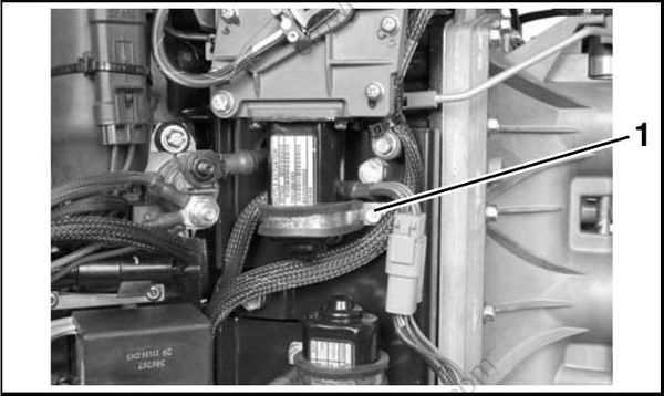
- Clamp retaining screw
Use Ball Socket Remover tool, P/N 342226, to remove throttle link from actuator arm.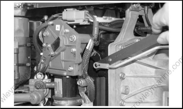
Remove the four throttle actuator retaining screws.
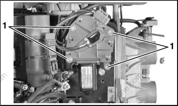
- Throttle actuator retaining screws
Installation
Remove old adhesive from clamp retaining screw and shift actuator retaining screws.
Apply Nut Lock on the threads of the screws.
Install throttle actuator on mounting plate with three long screws and one short screw. Tighten screws to a torque of 60 to 84 in. lbs. (7 to 9.5 N·m).
Do not install clamp until wiring harnesses have been secured.
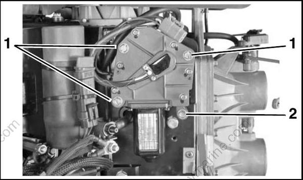
- Long screws
- Short screw
Use Ball Socket Installer tool, P/N 342225, to snap throttle link onto actuator arm.
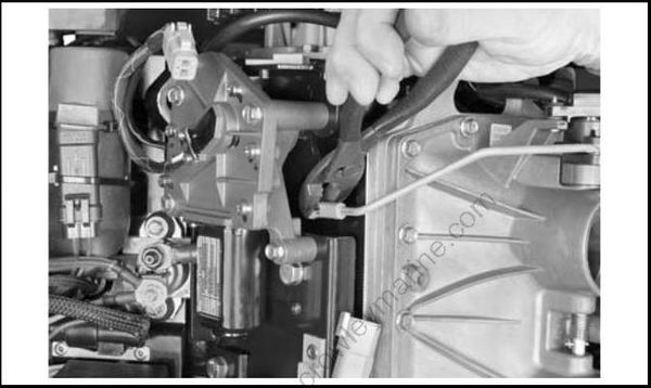
Secure ESM to throttle actuator harness with tie strap, P/N 320107.
Route ESM to shift actuator harness behind throttle actuator and over throttle actuator harness.
Place clamp over actuator motor. Install and tighten screw to a torque of 60 to 84 in. lbs. (7 to 9.5 N·m).
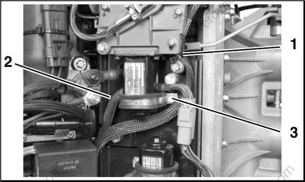
- Tie strap
- ESM to shift actuator harness
- Clamp retaining screw
Route the throttle actuator harness behind and over the oil recirculation hose as shown. Connect the throttle actuator harness. Attach to clip on mounting plate.
Make sure the oil recirculation hose is not pinched during assembly.
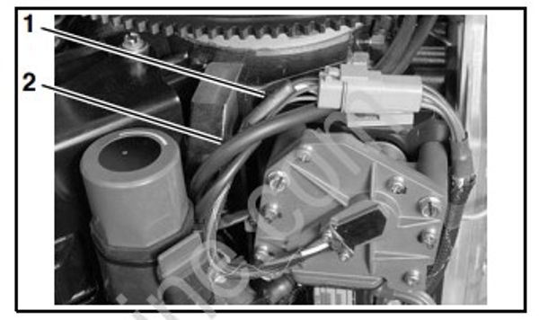
- Throttle actuator harness
- Oil recirculation hose
IMPORTANT: Calibrate actuator. Refer to Calibrate Actuator Stroke on p. 209.
