OILING SYSTEM
Observe oil flow through all oil distribution hoses. Air must be purged during the priming procedure.
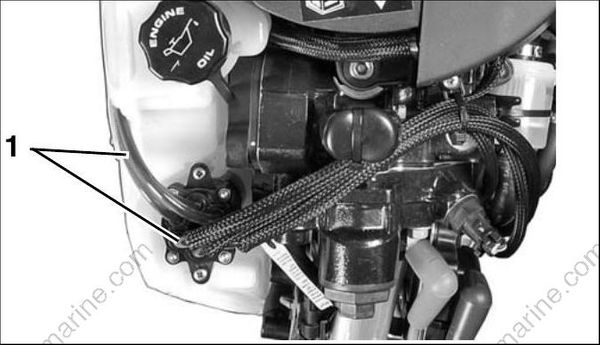
- Oil distribution hoses 007997
Small bubbles are acceptable. Large bubbles must be eliminated through continued priming.
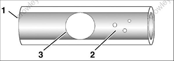
- Oil distribution hose
- Small bubbles
- Large bubbles
004398
Repair any fuel or oil leaks.
The oiling system on these models can also be primed using the Self-Winterizing feature if diagnostics software is not available. Refer to STOR- AGE on p. 49.
OILING SYSTEM TEST
IMPORTANT: Always perform visual inspections to identify oiling system leaks. Make sure the oil tank is filled and oil supply is not contaminated.
Oil Injection Pump Voltage Tests
IMPORTANT: Do NOT perform static tests using Diagnostic Power Supply Tool, P/N 587005, with internal 9 volt batteries only. This will produce false results. Refer to Communication on p. 67. The EMM controls the pump by providing ground through pin 23 (blue wire) of the J1-B connector and pin B (blue wire) of the oil pump connector.
| Key switch ON | approximately 12VDC |
|---|---|
| Control signal | approximately 5 Hz |
| Engine running | approximately 55VDC |
Use a digital multimeter calibrated to a scale that reads 12 V (DC) to measure voltage between the oil pump electrical connector and engine ground. Connect negative meter lead to ground.
Use an appropriate test probe to connect positive meter lead to pin B (blue wire) of oil injection pump electrical connector.
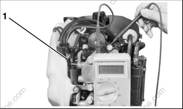
- Oil injection pump electrical connector 008065
Turn the key switch to the ON position. Observe voltage at pin B.
• Voltage at pin B should be approximately 12 V.
Use the Oil Injector test of Evinrude Diagnostic software Static Test screen to activate the oil pump
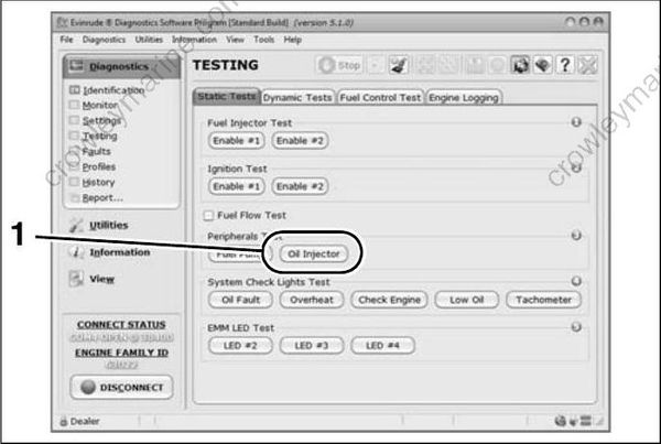
Static Tests Screen
- Oil injector test button
008082
IMPORTANT: This test is operating the pump with 12 V battery power on the system voltage (55 V) circuit. The oil injection pump will not pump oil when operating on 12 V. Observe voltage at pin B.
Observe voltage at pin B.
• Voltage at pin B should drop as the oil pump cycles.
Check the control signal while the Oil Injector test is running. Set the digital multimeter to the Hertz (Hz) scale.
• Meter should read approximately 5 Hz.
Results:
• If voltage and control signal readings at pin B are within range, the EMM and wiring are not at fault.
• If voltage at pin B is not within range, check voltage at pin A (white/red wire) of oil pump electrical connector.
Connect positive meter lead to pin A (white/red wire) of oil injection pump electrical connector. Observe voltage at pin A.
• Voltage at pin A should be approximately 12 V.
Set digital multimeter to a scale that reads 55 V (DC).
Start the engine. Observe voltage at pin A.
• Voltage at pin A should be approximately 55 V.
• If voltage at pin A is within range, refer to Oil Injection Pump Resistance Test on p. 171.
• No voltage reading at pin A, refer to System Voltage Test on p. 84.
Oil Injection Pump Resistance Test
Disconnect the battery cables at the battery.
Disconnect the electrical connector from the oil injection pump.
Use a digital multimeter to measure the resistance between the pins of the oil injection pump connector. Calibrate the meter to the LOW OHMS scale.
| Oil Injection Pump Circuit Resistance |
|---|
| 22 Ω |
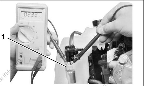
- Oil injection pump connector 008420
Results:
• An infinite reading (∞) indicates an open circuit of the injection pump winding. Replace faulty pump
Oil Injection Pump Function Test
Remove oil distribution hose from fitting at oil distribution manifold. Do not lose the brass hose sup port.
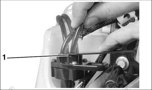
- Retainer mechanism 008067
Temporarily install a length of oil hose.
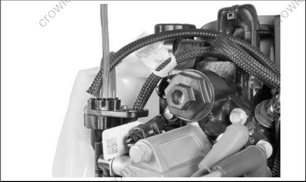
008068
Start the outboard and observe oil flow:
• Oil flows from hose, compare to oil flow at other distribution fittings
• If one or more fittings fail to flow oil, replace the oil injection pump assembly
Reinstall hose into manifold.
IMPORTANT: Make sure hose support is in hose and hose is fully inserted into manifold. Refer to Oil Distribution Hoses on p. 173.
Oil Injection Fittings Flow Test
Make sure the oil injection fittings of the cylinder and crankcase assembly allow fluid to move.
Remove oil distribution hose from oil distribution manifold.
Use a Syringe, P/N 346936, filled with isopropyl alcohol to force fluid through hose and fitting.
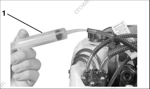
- Syringe 008069
LOW OIL Sending Unit Test
Remove oil from the oil tank.
Turn the key switch ON. The dash mounted Engine Monitor system should show a LOW OIL warning.
Once the warning has been confirmed, refill the oil tank and start the outboard. The LOW OIL warning should stop after the oil pump cycles 3 times.