STERN BRACKET – Power Tilt Models
Stern Bracket Disassembly (Power Tilt)
If outboard is equipped with a tiller arm, remove the tiller arm. Refer to TILLER HANDLE SER- VICE on p. 231.
Remove exhaust housing. Refer to EXHAUST HOUSING SERVICE on p. 207.
Remove lower mount bracket retaining screws.
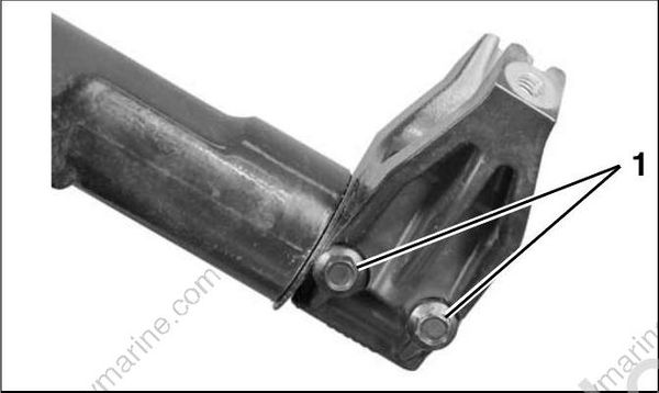
- Screws
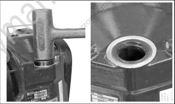
Use a soft mallet to remove lower mount bracket and thrust washer.
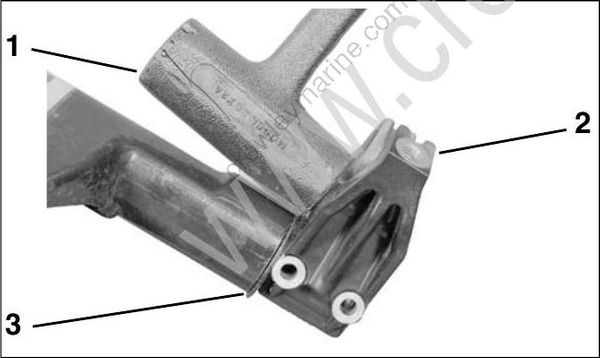
- Mallet
- Lower mount bracket
- Thrust washer
If equipped with a steering friction device, remove the steering friction nut.
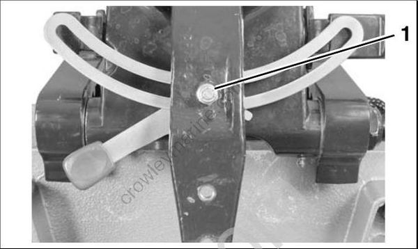
- Steering friction nut
Slide the steering arm out of the swivel bracket and remove the thrust washer .
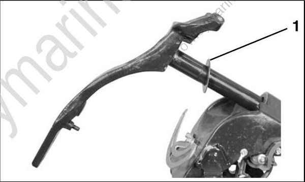
- Upper thrust washer
Remove the steering friction lever, washers and plate.
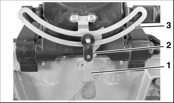
- Steering friction lever
- Steering friction washers
- Steering friction plate
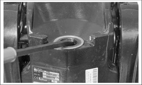
Use an appropriate tool to pry the upper and lower seals from the swivel bracket.
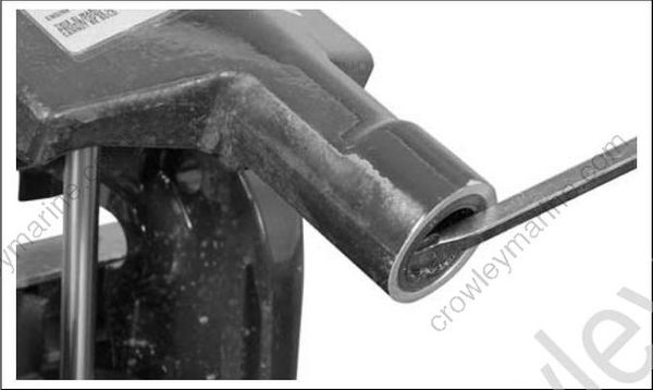
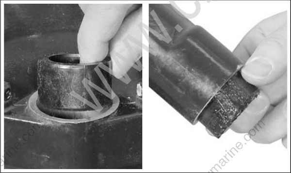
Remove the upper and lower bushings from the swivel bracket.
Raise the outboard and engage the tilt support.
Remove the electrical connector from the trim sending unit. Refer to CONNECTOR SERVICING on p. 111.
Remove the trim/tilt cable connector. Refer to TRIM AND TILT REPLACEMENT on p. 277.
Remove the clip from the cylinder pin.
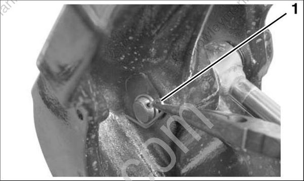
- Clip
Remove one of the locknuts from the angle adjustment rod.
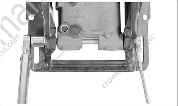
Remove the tie bar
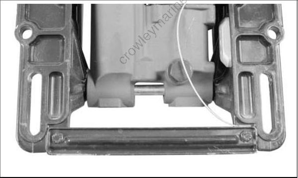
Remove angle adjustment rod and remove the hydraulic unit.
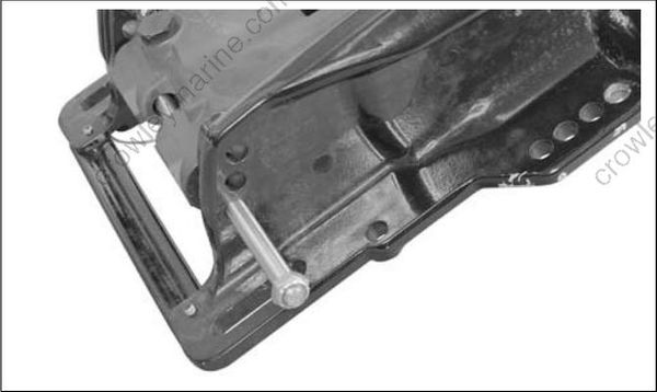
To separate stern and swivel brackets, remove tilt tube nuts, tilt tube, bushings, thrust washers, and cable clamp.
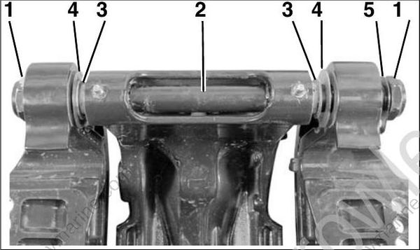
- Tilt tube nuts
- Tilt tube
- Bushings
- Thrust washers
- Cable clamp
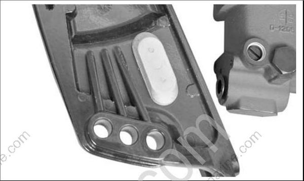
Check the condition of the anode. Replace the anode if it has been reduced to two-thirds its original size.
Stern Bracket Assembly (Power Tilt)
Assemble stern and swivel brackets with tilt tube nuts, tilt tube, bushings, thrust washers, and cable clamp.
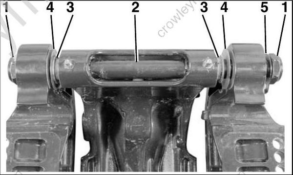
- Tilt tube nuts
- Tilt tube
- Bushings
- Thrust washers
- Cable clamp
Make sure cable clamp is positioned as shown.
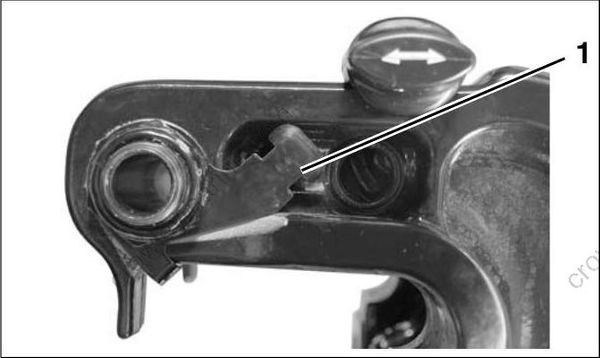
- Cable clamp
Route the hydraulic unit and trim sender harnesses through the grommet in the port stern bracket.
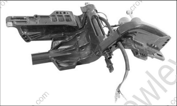
Secure harness in wire clamp as shown.
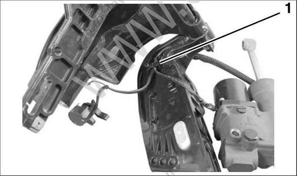
- Wire clamp
Install bushings in hydraulic unit. Position hydraulic unit between stern brackets and install the angle adjustment rod.
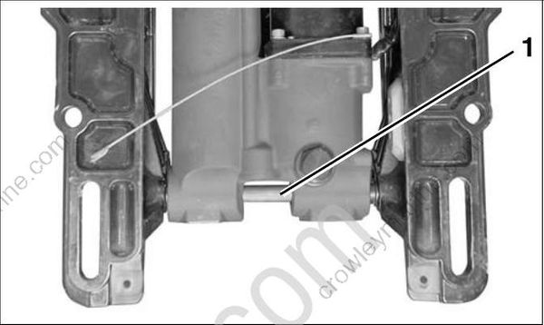
- Angle adjustment rod
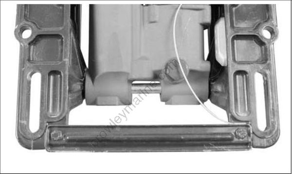
Place the ground lead between the port stern bracket and tie bar as shown. Assemble the tie bar to the stern brackets. Apply Ultra Lock to the threads of the tie bar screws. Install the screws and tighten to a torque of 144 to 168 in. lbs. (16 to 19 N•m).
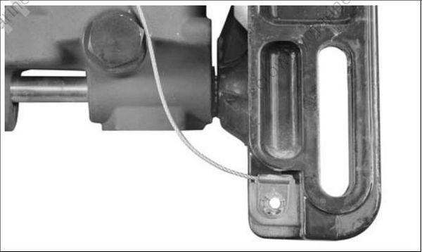
Install the cylinder pin and secure with clip.
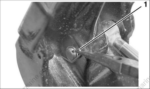
- Clip
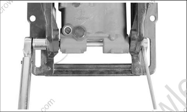
Tighten the locknuts to a torque of 60 to 84 in. lbs. (7 to 9.5 N•m).
Install the trim sending unit. Refer to Trim Sending Unit Installation on p. 219.
Apply a light coat of Triple-Guard grease to the outside of the upper and lower bushings.
Install the upper and lower bushings in the swivel bracket.
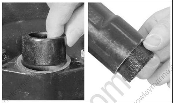
Use Seal Installation tool, P/N 350958, to install new upper and lower seals in the swivel bracket. Install seals with lips of seals facing in.
Install the steering friction plate, washers and lever.
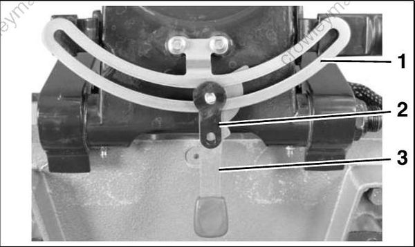
- Steering friction plate
- Steering friction washers
- Steering friction lever
Apply Triple-Guard grease to both sides of thrust washer. Install thrust washer on steering arm.
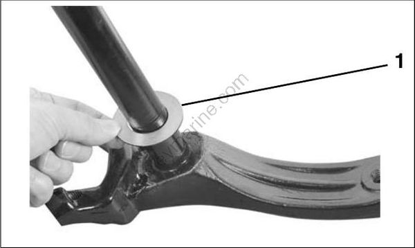
- Thrust washer
Slide the steering arm with thrust washer through the swivel bracket.
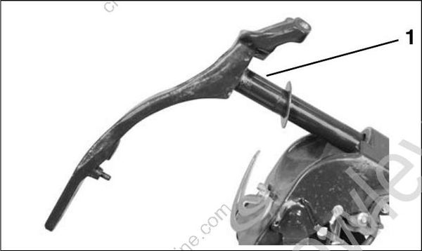
- Upper thrust washer
Align slots of friction washers with dowel pin.
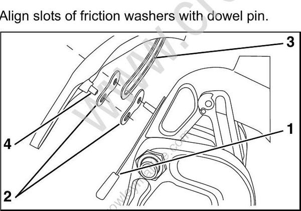
- Steering friction lever
- Friction washers
- Friction plate
- Dowel pin
Align dowel pin and steering friction lever as shown.
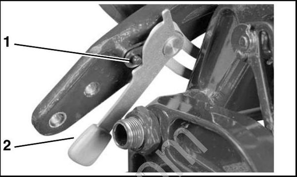
- Dowel pin
- Steering friction lever
Install locking nut. Temporarily tighten locking nut three to four full turns. Final adjustment will be performed later.
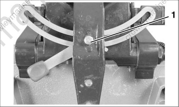
- Steering friction nut
Apply Triple-Guard grease to both sides of thrust washer. Install thrust washer on steering arm.
Install lower mount bracket on steering arm.
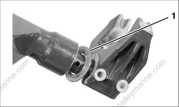
- Thrust washer
Install lower mount retaining screws. Tighten screws to a torque of 10 to 12 ft. lbs. (14.5 to 16.5 N•m).
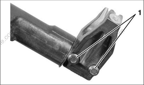
- Retaining screws
Tighten the tilt tube nuts to a torque of 40 to 45 ft. lbs. (54 to 61 N•m), then back off 1/8 to 1/4 turn.
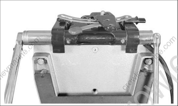
Install exhaust housing. Refer to EXHAUST HOUSING SERVICE on p. 207.
Install tiller handle. Refer to TILLER HANDLE SERVICE on p. 231.
Adjust tiller steering friction. Refer to Steering Friction Adjustment on p. 26.
Trim Sending Unit Removal
Remove two screws. Remove sending unit and washers from swivel bracket.
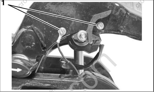
- Screws
Remove trim sender electrical connector from harness. Refer to CONNECTOR SERVICING on p. 111.
Remove tie straps from harness. Pull harness from stern bracket to remove sending unit.
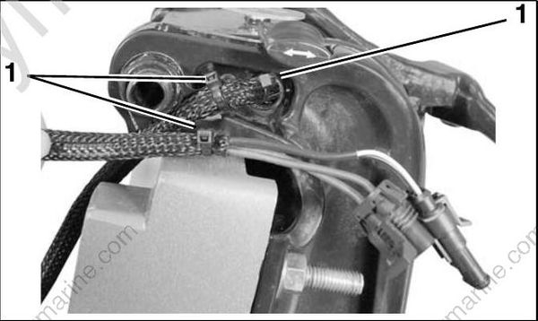
- Tie straps
Trim Sending Unit Installation
Route trim sending unit harness through port stern bracket grommet. Secure harness in wire clamp as shown.
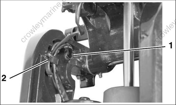
- Grommet
- Wire clamp
Place rear screw through hole. Place two washers on rear screw. Position sending unit and install rear screw.
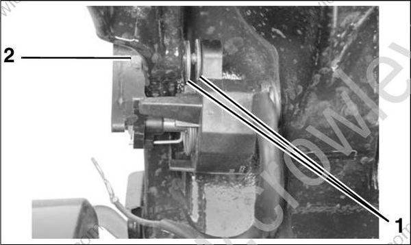
- Washers
- Rear screw
Place ground wire over front screw and install front screw. Tighten screws to a torque of 10 to 16 in. lbs. (1 to 2 N•m).
When reinstalling screws in composite materials turn screws COUNTER-CLOCK- WISE until threads of screw engage threads of screw boss.
Failure to follow this procedure will dam- age the screw boss threads. Once threads are engaged, tighten screws securely.
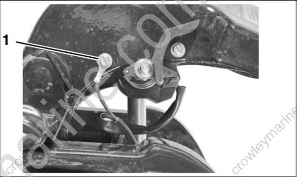
- Front screw
Install trim sender electrical connector on harness. Refer to CONNECTOR SERVICING on p. 111.
Install tie straps on cable clamp and harness.
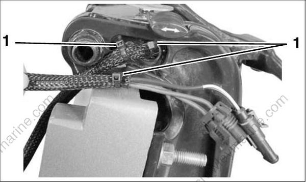
- Tie straps
IMPORTANT: Operate trim unit and make sure the wiring harness will not be damaged between stern and swivel brackets.