

STERN BRACKET – Manual Tilt Models
Clamp Screw Service
Inspect clamp screw assemblies. Replace swivel plate and shoulder screw if bent or loose.
Disassemble swivel plate and shoulder screw.
Inspect and clean clamp screw and shoulder bolt threads.
Install clamp screw and handle assembly in transom bracket.
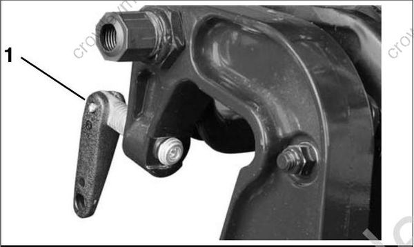
- Clamp screw and handle assembly
Install swivel plate, onto shoulder screw.
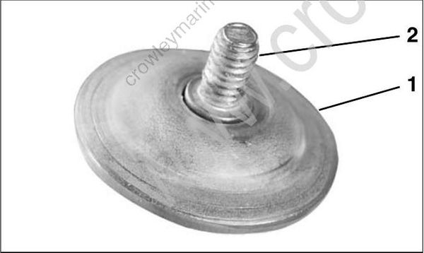
- Swivel plate
- Shoulder screw
Apply Locquic Primer to the threads of the screw and allow it to dry four to five minutes. Then apply Ultra Lock to threads.
Install shoulder screw and swivel plate onto clamp screw and handle assembly.
Tighten screw to a torque of 60 to 84 in. lbs. (7.5 to 9 N•m).
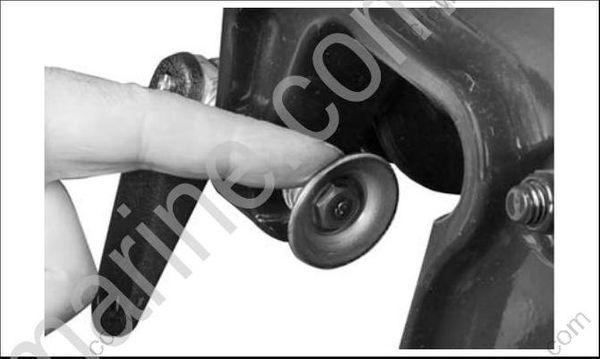
Check for free movement of swivel plate on shoulder bolt.
Stern Bracket Disassembly (Manual Tilt)
If outboard is equipped with a tiller arm, remove the tiller arm. Refer to TILLER HANDLE SERVICE on p. 227.
Remove exhaust housing. Refer to EXHAUST HOUSING SERVICE on p. 203.
Remove lower mount bracket retaining screws.
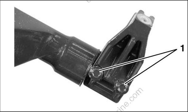
- Screws
Use a soft mallet to remove lower mount bracket and thrust washer.
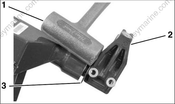
- Mallet
- Lower mount bracket
- Thrust washer
If equipped with a steering friction device, remove the steering friction nut.
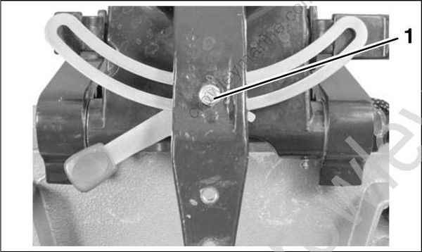
- Steering friction nut
Slide the steering arm out of the swivel bracket and remove the thrust washer.
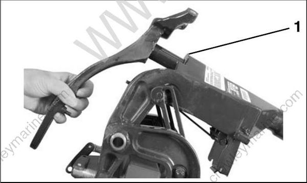
- Upper thrust washer
Remove the steering friction lever, washers and plate.
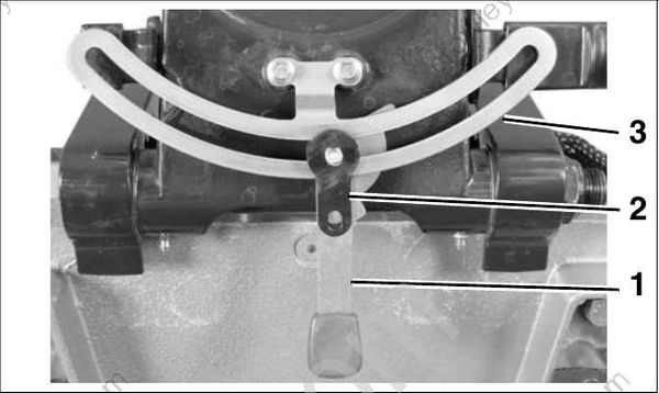
- Steering friction lever
- Steering friction washers
- Steering friction plate
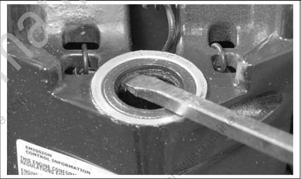
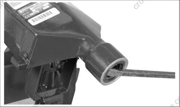
Use an appropriate tool to pry the upper and lower seals from the swivel bracket.
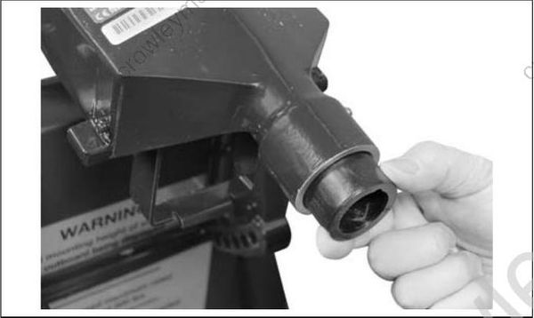
Remove the friction screw and spring. Remove upper and lower bushings from the swivel bracket.
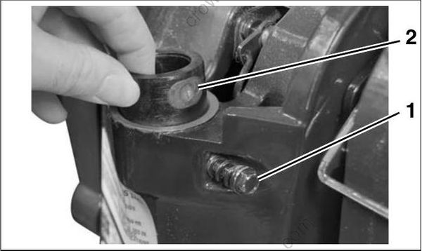
- Friction plate
- Friction screw
Loosen tilt tube nuts four to five turns.
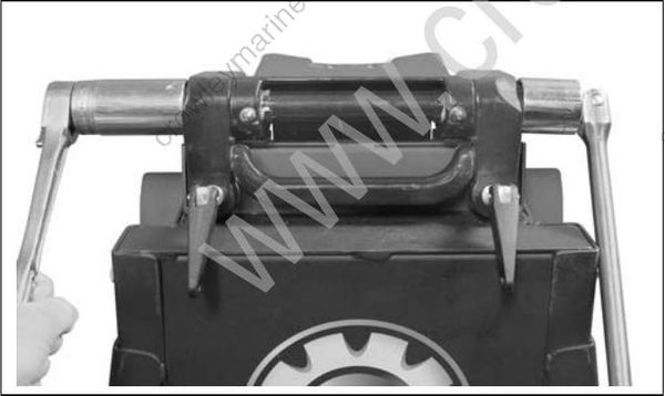
Remove the tilt pin, two tie bar screws and tie bar.
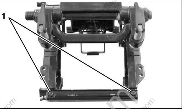
- Tie bar screws
Remove nuts, washers and pins from stern brackets.
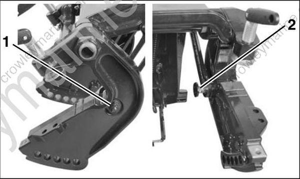
- Nut and washer
- Pin
Remove tilt tube nuts, tilt tube, bushings, thrust washers, handle and stern brackets.
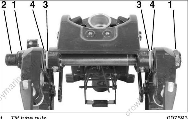
- Tilt tube nuts
- Tilt tube
- Bushings
- Thrust washers
Use an appropriate tool to unhook the two springs from the top of the swivel bracket. Remove the springs.
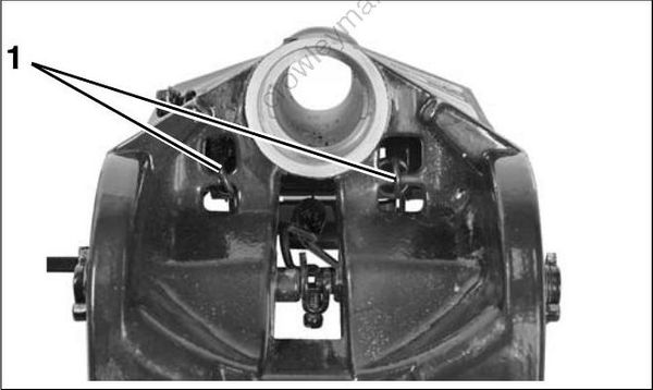
- Springs
Unhook spring from reverse lock release rod.
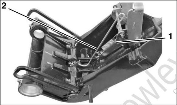
- Spring
- Reverse lock release rod
Place the tilt/run lever in the RUN position. Loosen the bellcrank setscrew.
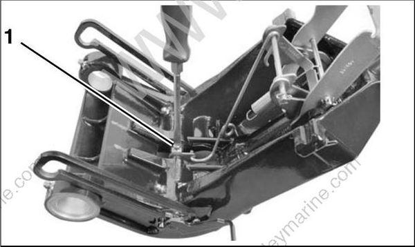
- Bellcrank setscrew
Push down on link. Unhook reverse lock release rod from pin and remove rod from bellcrank.
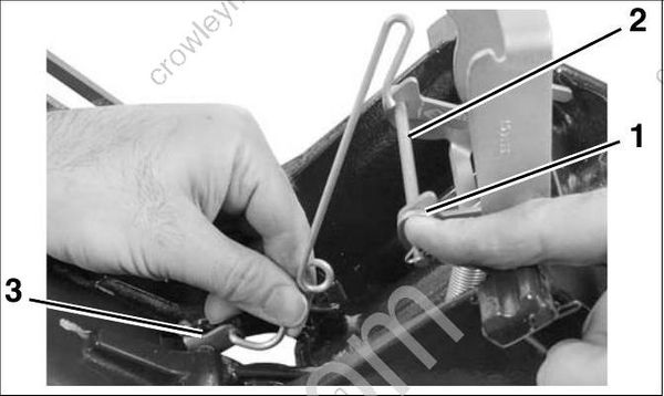
- Link
- Pin
- Bellcrank
Remove the bellcrank, tilt lock lever, and port stop link from the swivel bracket
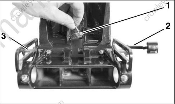
- Bellcrank
- Tilt lock lever
- Stop link
Remove retaining clips from both sides of the swivel bracket.
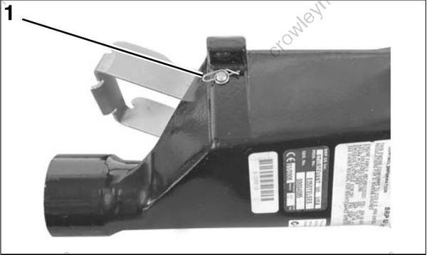
- Clip
Remove pins from shallow water drive link and swivel bracket. Use care not to lose spring.
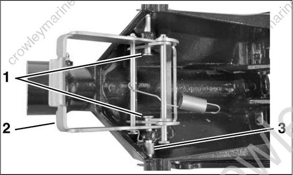
- Pins
- Shallow water drive link
- Spring
Remove the shallow water drive link and reverse lock assembly from the swivel bracket.
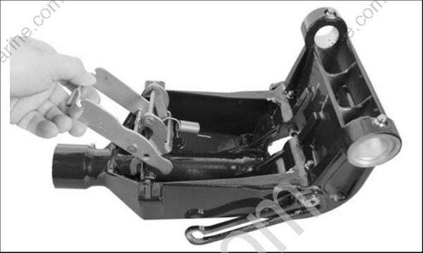
Remove cotter pin s and disassemble shallow water drive and reverse lock assembly as needed.
If tilt lock assembly requires replacement, use an appropriate tool to remove bushing from swivel bracket.
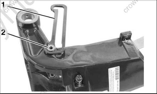
- Tilt lock assembly
- Bushing
Stern Bracket Assembly (Manual Tilt)
Install a new bushing through hole in tilt lock assembly. Press bushing into swivel bracket until fully seated. Make sure tilt lock assembly moves freely.
IMPORTANT: Prevent damage to the tilt lock assembly stop pin. Be sure to properly support the swivel bracket when pressing in bushings.
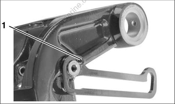
- Stop pin
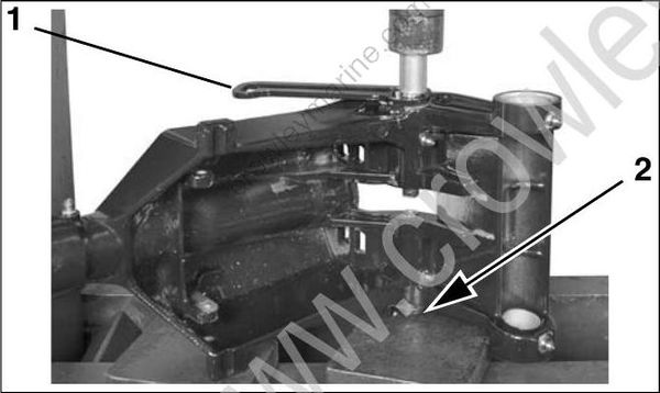
- Tilt lock assembly
- Correct support
Assemble reverse lock link and reverse lock lever as shown. Install pin and secure with new cotter pin.
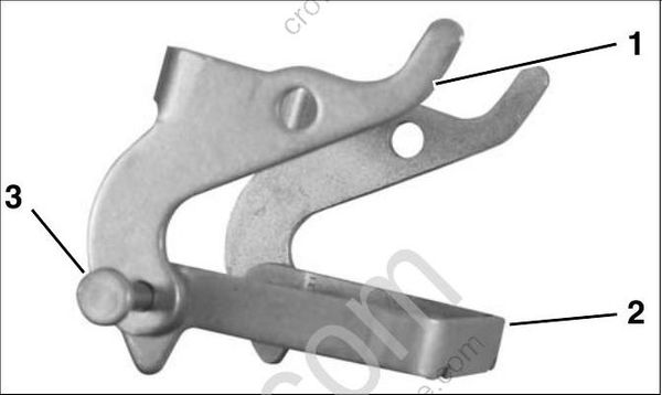
- Reverse lock link
- Reverse lock lever
- Pin
Place pin through the shallow water drive link as shown. Secure with new cotter pin.
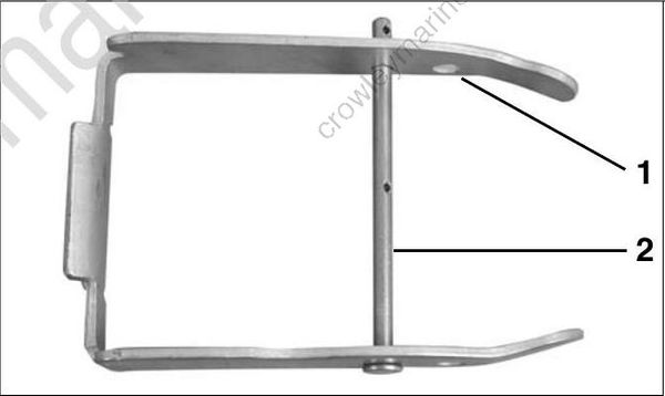
- Shallow water drive link
- Pin
Align reverse lock link assembly with shallow water drive link as shown.
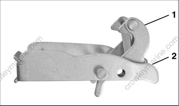
- Reverse lock link assembly
- Shallow water drive link
Place the shallow water drive link and reverse lock assembly into the swivel bracket as shown Install one pin as shown and secure pin with clip.
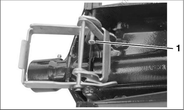
- Pin
Install remaining pin through reverse lock assembly and into boss. Use an appropriate tool to hold spring in alignment. Push pin through spring and swivel bracket. Secure pin with clip.
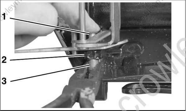
- Pin
- Boss
- Spring
IMPORTANT: Make sure the rounded end of the spring is installed as shown.
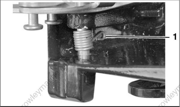
- Spring rounded end
Use an appropriate tool to hook the straight end over the pin as shown.
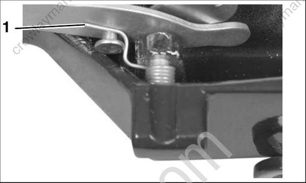
- Spring straight end
Install the tilt lock lever and port stop link in the swivel bracket. Install the bellcrank, temporarily leave the bell crank screw loose.
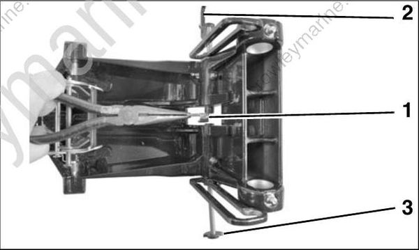
- Bellcrank
- Tilt lock lever
- Stop link
Be sure the tilt lock lever cam and port stop link cam are installed as shown.
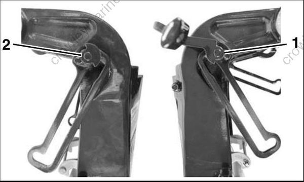
- Port stop link cam
- Tilt lock lever cam
Install reverse lock release rod on bellcrank. Connect rod to pin as shown.
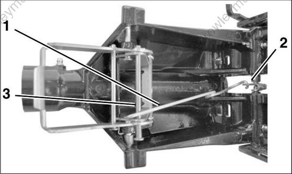
- Reverse lock release rod
- Bellcrank
- Pin
Tighten the bellcrank setscrew to a torque of 35 to 61 in. lbs. (4 to 7 N•m).
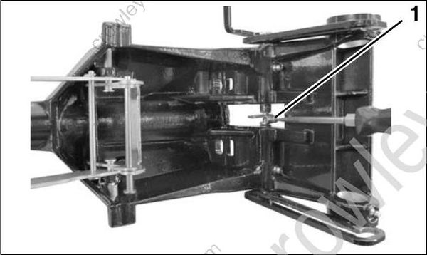
- Bellcrank setscrew
Connect the hook end of spring to the reverse lock release rod.
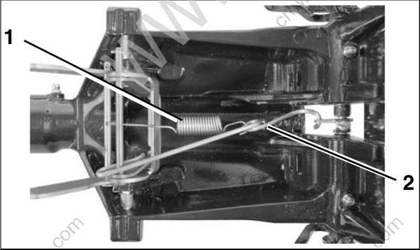
- Spring
- Reverse lock release rod
Attach the two reverse lock springs to the reverse lock lever.
Use an appropriate tool to connect the reverse lock springs to the top of the swivel bracket.
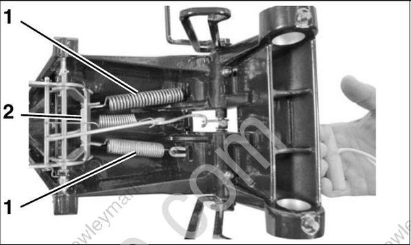
- Springs
- Reverse lock lever
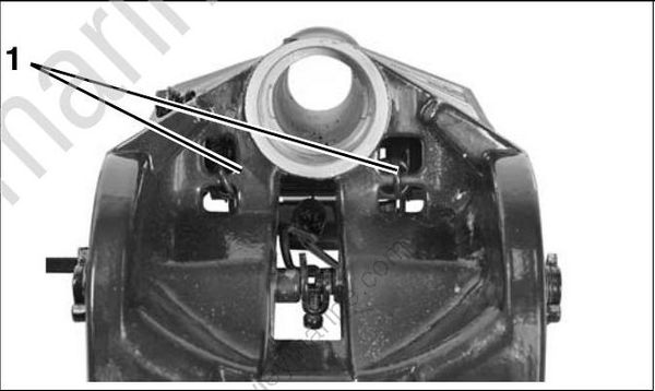
- Springs
Install tilt tube, bushings, thrust washers, handle and stern brackets.
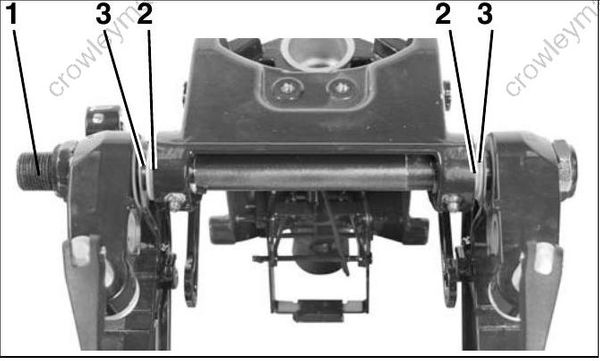
- Tilt tube
- Bushings
- Thrust washers
Install pin through each lock assembly and stern bracket. Install washers and nuts, and tighten to a torque of 18 to 20 ft. lbs. (24.5 to 27 N•m).
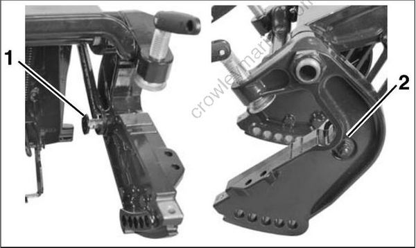
- Pin
- Nut and washer
Apply Ultra Lock to the threads of the tie bar screws. Install the screws and tighten to a torque of 144 to 168 in. lbs. (16 to 19 N•m). Install the tilt pin.
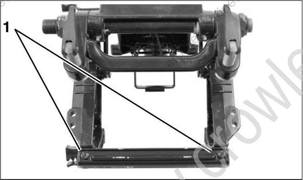
- Tie bar screws
Tighten the tilt tube nuts to a torque of 40 to 45 ft. lbs. (54 to 61 N•m), then back off 1/8 to 1/4 turn.
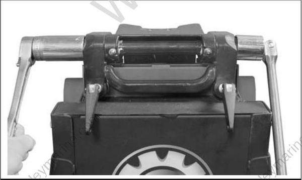
Install friction screw and spring in swivel bracket.
Apply a light coat of Triple-Guard grease to the outside of the upper bushing.
Install upper bushing. Make sure bushing slots are aligned with slots in swivel bracket.
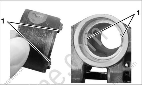
- Slots
Make sure friction plate is aligned toward friction screw.
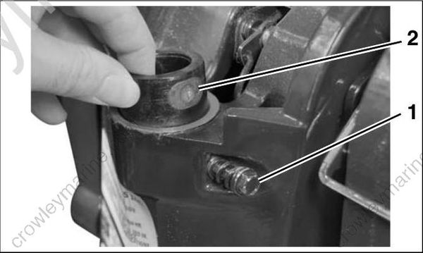
- Friction plate
- Friction screw
Apply a light coat of Triple-Guard grease to the outside of the lower bushing. Install bushing in the swivel bracket.
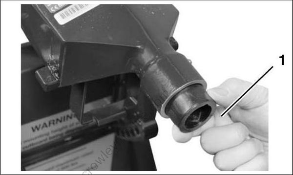
- Lower bushing
Use Seal Installation tool, P/N 350958, to inst all new upper and lower seals in the swivel bracket. Install seals with lips of seals facing in.
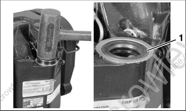
- Seal
Install the steering friction plate, washers and lever.
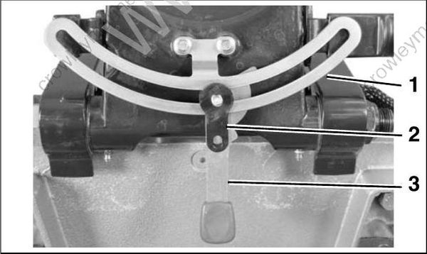
- Steering friction plate
- Steering friction washers
- Steering friction lever
Apply Triple-Guard grease to both sides of thrust washer. Install thrust washer on steering arm.
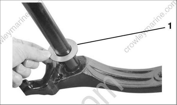
- Thrust washer
Slide the steering arm through the swivel bracket.
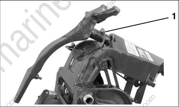
- Thrust washer
Align slots of friction washers with dowel pin.
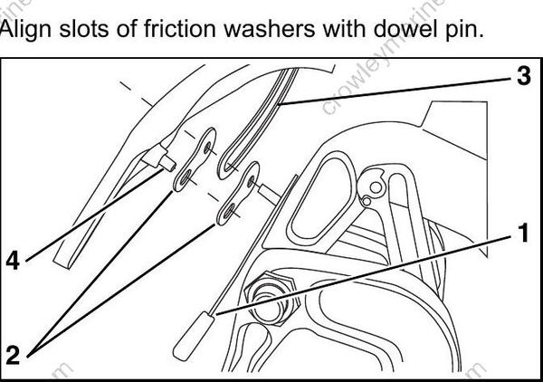
- Steering friction lever
- Friction washers
- Friction plate
- Dowel pin
Align dowel pin and steering friction lever as shown.
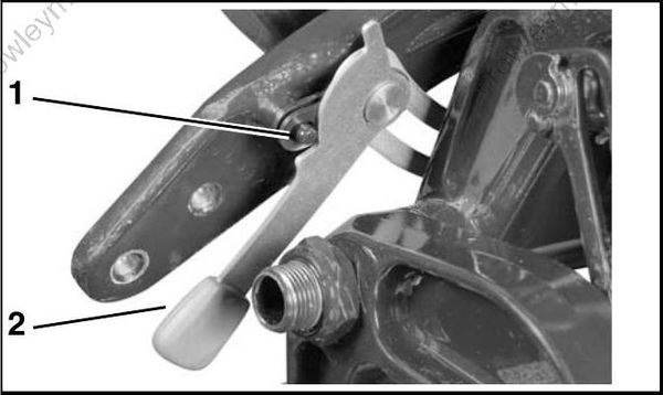
- Dowel pin
- Steering friction lever
Install locking nut. Temporarily tighten locking nut three to four full turns. Final adjustment will be performed later.
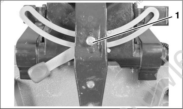
- Steering friction nut
Lubricate the swivel bracket through the four lubrication fittings with Triple-Guard grease.
Apply Triple-Guard grease to both sides of thrust washer. Install thrust washer on steering arm.
Install lower mount bracket on steering arm.
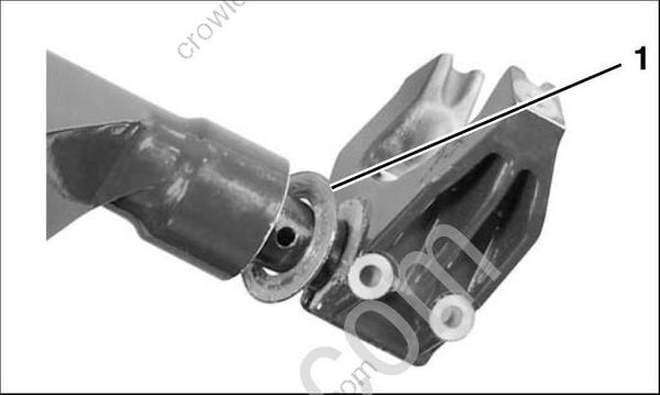
- Thrust washer
Install lower mount retaining screws. Tighten screws to a torque of 10 to 12 ft. lbs. (14.5 to 16.5 N•m).
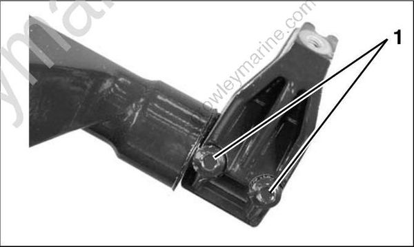
- Retaining screws
Install exhaust housing . Refer to EXHAUST HOUSING SERVICE on p. 203.
Install tiller handle. Refer to TILLER HANDLE SERVICE on p. 227.
Adjust tiller steering friction. Refer to Steering Friction Adjustment on p. 24.
