

Step 1: MODELS COVERED IN THIS MANUAL
This manual covers service information on all 90° V6 Evinrude E-TEC™ models.
| ModelNumber | Shaft | Paint | HP |
|---|---|---|---|
| E200HSLSUC | 20” | WH | 200 |
| E200DHLSUG | 20” | BL | 200 |
| E200DHLSUA | 20” | BL | 200 |
| E200DHXSUC | 25” | WH | 200 |
| E200HCXSUC | 25” | WH | 200 |
| E225DPLSUG | 20” | BL | 225 |
| E225DPLSUA | 20” | BL | 225 |
| E225DPXSUG | 25” | WH | 225 |
| E225DPXSUA | 25” | WH | 225 |
| E225DPZSUA | 30” | WH | 225 |
| E225DCXSUA | 25” | WH | 225 |
| E225DCZSUG | 30” | WH | 225 |
| E225DCZSUG | 30” | WH | 225 |
| E225DHLSUG | 20” | BL | 225 |
| E225DHLSUA | 20” | BL | 225 |
| E225DHXSUG | 25” | BL | 225 |
| E225DHXSUR | 25” | BL | 225 |
| E250DPLSUA | 20” | BL | 250 |
| E250DPXSUG | 25” | WH | 250 |
| E250DPXSUA | 25” | WH | 250 |
| E250DPZSUG | 30” | WH | 250 |
| E250DPZSUA | 30” | WH | 250 |
| E250DCXSUG | 25” | WH | 250 |
| E250DCXSUA | 25” | WH | 250 |
| E250DCZSUA | 30” | WH | 250 |
Identifying Model and Serial Numbers
Outboard model and serial numbers are located on the swivel bracket and on the powerhead.

Swivel Bracket
- Model and serial number

- Serial number
Step 2: MODEL DESIGNATION

Step 3: TYPICAL PAGE – A

Step 4: TYPICAL PAGE – B

Step 5: TYPICAL PAGE – C

Step 6: TYPICAL PAGE – D

Step 7: ABBREVIATIONS USED IN THIS MANUAL
Units of Measurement
| A | Amperes |
| amp-hr | Ampere hour |
| fl. oz. | fluid ounce |
| ft. lbs. | foot pounds |
| HP | horsepower |
| in. | inch |
| in. Hg | inches of mercury |
| in. lbs. | inch pounds |
| kPa | kilopascals |
| ml | milliliter |
| mm | millimeter |
| N·m | Newton meter |
| P/N | part number |
| psi | pounds per square inch |
| RPM | revolutions per minute |
| °C | degrees Celsius |
| °F | degrees Fahrenheit |
| ms | milliseconds |
| µs | microseconds |
| Ω | Ohms |
| V | Volts |
| VAC | Volts Alternating Current |
| VDC | Volts Direct Current |
List of Abbreviations
| ABYC | American Boat & Yacht Council |
| ATDC | after top dead center |
| AT | air temperature sensor |
| BPS | barometric pressure sensor |
| BTDC | before top dead center |
| CCA | cold cranking amps |
| CPS | crankshaft position sensor |
| DI | Direct-Injection |
| ECU | electronic control unit |
| EMM | engine management module |
| ICOMIA | International Council of Marine Industry Associations |
| MCA | marine cranking amps |
| MWS | modular wiring system |
| NMEA | National Marine Electronics Assoc. |
| NTC | negative temperature coefficient |
| PDP | power distribution panel |
| PTC | positive temperature coefficient |
| ROM | read only memory |
| S.A.F.E.™ | speed adjusting failsafe electronics |
| SAC | start assist circuit |
| SAE | Society of Automotive Engineers |
| S.L.O.W.™ | speed limiting operational warning |
| SYNC | synchronization |
| TDC | top dead center |
| TPS | throttle position sensor |
| WOT | wide open throttle |
| WTS | water temperature sensor |
Step 8: ENGINE EMISSIONS INFORMATION
Maintenance, replacement, or repair of the emission control devices and systems may be performed by any marine SI (spark ignition) engine repair establishment or individual.
Manufacturer’s Responsibility
Beginning with 1999 model year outboards, manufacturers of marine outboards must determine the exhaust emission levels for each outboard horsepower family and certify these outboards with the United States of America Environmental Protection Agency (EPA). An emissions control information label, showing emission levels and outboard specifications, must be placed on each outboard at the time of manufacture.
Dealer’s Responsibility
When performing service on all 1999 and more recent Evinrude/Johnson outboards that carry an emissions control information label, adjustments must be kept within published factory specifications.
Replacement or repair of any emission related component must be executed in a manner that maintains emission levels within the prescribed certification standards.
Dealers are not to modify the outboard in any manner that would alter the horsepower or allow emission levels to exceed their predetermined factory specifications.
Exceptions include manufacturer’s prescribed changes, such as altitude adjustments, for example.
Owner’s Responsibility
The owner/operator is required to have outboard maintenance performed to maintain emission levels within prescribed certification standards.
The owner/operator is not to, and should not allow anyone to, modify the outboard in any manner that would alter the horsepower or allow emissions levels to exceed their predetermined factory specifications.
Tampering with the fuel system to change horsepower or modify emission levels beyond factory settings or specifications will void the product warranty.
EPA Emission Regulations
All new 1999 and more recent Evinrude/Johnson outboards are certified to the EPA as conforming to the requirements of the regulations for the control of air pollution from new watercraft marine spark ignition outboards. This certification is contingent on certain adjustments being set to factory standards. For this reason, the factory procedure for servicing the product must be strictly followed and, whenever practical, returned to the original intent of the design. The responsibilities listed above are general and in no way a complete listing of the rules and regulations pertaining to the EPA requirements on exhaust emissions for marine products. For more detailed information on this subject, you may contact the following locations:
VIA U.S. POSTAL SERVICE:
Office of Mobile Sources
Engine Programs and Compliance Division
Engine Compliance Programs Group (6403J)
401 M St. NW
Washington, DC 20460
VIA EXPRESS or COURIER MAIL:
Office of Mobile Sources
Engine Programs and Compliance Division
Engine Compliance Programs Group (6403J)
501 3rd St. NW
Washington, DC 20001
EPA INTERNET WEB SITE:
www.epa.gov
Step 9: PRODUCT REFERENCE AND ILLUSTRATIONS
BRP US Inc. reserves the right to make changes at any time, without notice, in specifications and models and also to discontinue models. The right is also reserved to change any specifications or parts, at any time, without incurring any obligation to equip same on models manufactured prior to date of such change. Specifications used are based on the latest product information available at the time of publication.
The continuing accuracy of this manual cannot be guaranteed.
All photographs and illustrations used in this manual may not depict actual models or equipment, but are intended as representative views for reference only.
Certain features or systems discussed in this manual might not be found on all models in all marketing areas.
All service technicians must be familiar with nautical orientation. This manual often identifies parts and procedures using these terms.

Nautical Orientation
Step 10: SYMBOLS
Throughout this service manual, symbols are used to interpret electrical troubleshooting results or to assign values in drawings.
Electrical
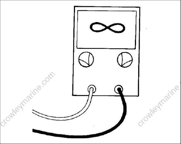
When “∞” shows on the meter face, no continuity, or very high resistance, is indicated. The symbol is referred to as infinity.
When “V” follows a value on the meter face, the procedure is measuring voltage.

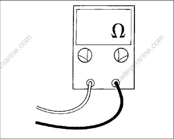
When “Ω” follows a value on the meter face, the procedure is measuring resistance. Ω is the symbol for ohm, the unit of measurement for resistance.
Values
When “≤” precedes a value on the meter face, the reading should be less than, or equal to, the value shown.
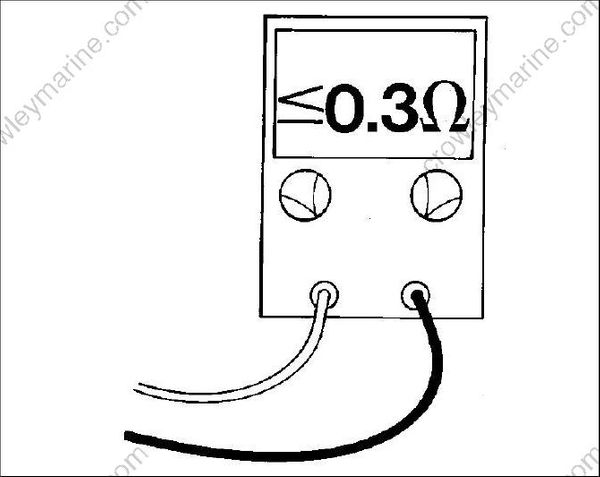
SYMBOLS When “≥” precedes a value on the meter face, the reading should be greater than, or equal to, the value shown.

