COMPONENTS
The oiling system consists of the following components:
• Oil tank
• Oil injection pump and manifold assembly
• Oil pressure sensor
• Electrical circuit
• LOW OIL (System Check) and NO OIL warning signals (EMM LED’s,System Check and I Command)
• Cylinder and crankcase
• Rear oil manifold assembly
• Oil recirculation system
Oil Tank
The oil tank must be properly positioned and the oil supply must be properly monitored. Refer to installation instructions provided with oil tank and Oiling System Set-Up on p. 43 for additional information.
Oil Tank Components
• Tank, 1.8 or 3.0 gallon capacity
• Oil pickup assembly (included with tank)
• Fill cap (included with tank)
• Mounting bracket and hardware
• Protective cover (1.8 gallon tank only)
• Hose clamp
• Hose plug
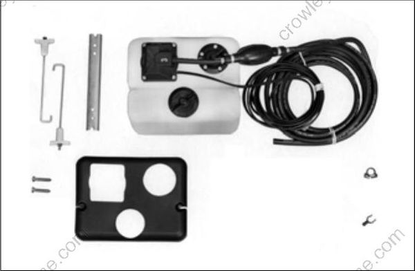
1.8 Gallon Oil Tank Kit
Oil Pick-up Components
• Pickup hose
• Sending unit, LOW OIL warning, and oil pickup
• Filter
• Primer bulb and supply hose
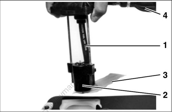
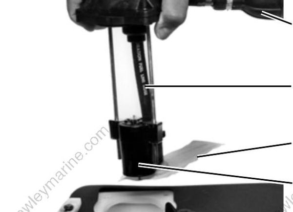
- Pickup hose
- Sending unit
- Filter
- Primer bulb and oil supply hose
Oil Injection Pump
The oil injection pump is an electric (55 V) actuator style pump. It draws oil from the oil tank through the oil supply hose [25 ft. (7.6 m) maxi mum] and supplies pressurized oil to the oil manifold. The EMM supplies 55 V and controls activation of the pump.
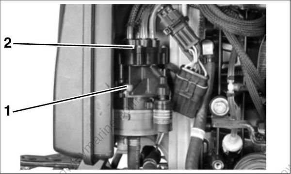
- Oil injection pump
- Oil manifold
The oil manifold distributes the oil supplied by the oil injection pump. A pressure-sensor monitors the oil injection pressure. Refer to Oil Injection Pump Diagram on p. 203
Oil Pressure Sensor
The oil pressure sensor reacts to changes in oil manifold pressure. The EMM supplies and monitors electrical current to the sensor.

- Oil pressure sensor
The sensor provides an output voltage to the EMM based on oil manifold pressures.
Oil Pressure Sensor Information:
| 5 VDC Input on RED wire |
|---|
| 0.5 - 4.5 V Output on TAN / WHITE wire |
| Ground on BLACK wire |
The EMM monitors the oil pressure sensor’s electrical circuit. If circuit voltage is beyond the specified range (< 0.12 V, > 4.88 V), the EMM :
| Stores a service code 71 |
|---|
| Initiates EMM SENSOR FAULT (LED 3) |
If oil pressure is below expected range (< 0.5 V), the EMM :
| Stores a service code 73 |
|---|
| Initiates EMM SENSOR FAULT (LED 3) |
If oil pressure is above expected range (> 4.5 V), the EMM :
| Stores a service code 73 |
|---|
| Initiates EMM SENSOR FAULT (LED 3) |
Refer to Oil Pressure Sensor on p. 99.
Electrical Circuit (55 V)
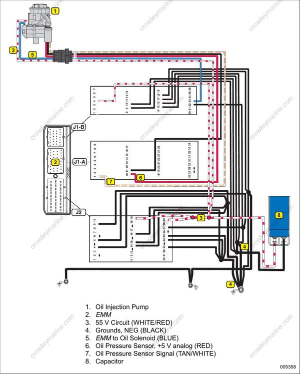
The oil injector is powered by the 55 V electrical circuit. The EMM controls injection pump operation by opening and closing the circuit’s ground. Circuit components:
• Oil injection pump winding
• Main wire harness and connections
• EMM, oil injection pump control function
• System voltage (55 V): stator, rectifier/regulator (EMM)
• Ground circuits, EMM and oil injection pump
Refer to Oiling System Electrical Diagram on p. 204 and OILING SYSTEM TESTS on p. 218.
The EMM monitors the oil injection pump electrical circuit. If circuit voltage is beyond the specified range (open circuit), the EMM:
| Activates S.A.F.E. |
|---|
| Initiates and stores a service code 34 |
| Initiates EMM NO OIL/OVERHEAT FAULT (LED 4) |
| Initiates the SystemCheck or I-Command “NO OIL” warning |
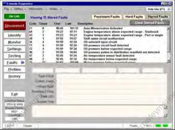
Stored Faults Review Screen
Oil Injection Pump Diagram

- Oil supply hose
- Inlet check valve
- Oil injection pump
- Injection pump check valve
- Oil distribution manifold
- Filter (screen type)
- Oil pressure sensor
- Oil distribution hoses to individual cylinders
- Oil distribution hose to rear manifold
Oiling System Electrical Diagram
SystemCheck, I-Command and EMM Oiling System Warnings
Evinrude outboards can be monitored by System Check or Evinrude E-TE 115-250 HP outboards can be equipped with the I-Command Integrated Performance System (CANbus network based on NMEA 2000 † standards.) Both systems warn the operator of a “NO OIL” condition.
LOW OIL Warning
A sending unit in the oil tank pick-up assembly monitors the oil level in the tank. This sending unit is designed to activate the System Check “LOW OIL” light when the oil level falls below one quarter capacity.
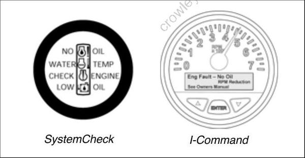
Warning System Gauges
An optional oil tank sending unit kit is available to interface with the I Command System. The I Command System does not provide a “LOW OIL” warning.
NO OIL Warning
The EMM monitors the electrical circuit of the oil pressure sensor. If the sensor or circuit fails, or if there is a lack of oil pressure in the oil distribution manifold, the EMM :
| Activates S.A.F.E. |
|---|
| Stores a service code 38 |
| Initiates EMM NO OIL/OVERHEAT FAULT (LED 4) |
| Initiates the System Check or I-Command “NO OIL” warning |
Refer to External Sensors on p. 98.
Cylinder and Crankcase
The primary oil distribution manifold provides crankcase lubrication through oil distribution hoses and pressed-in fittings at the front of the crankcase, port side.
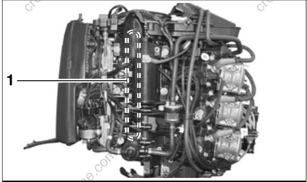
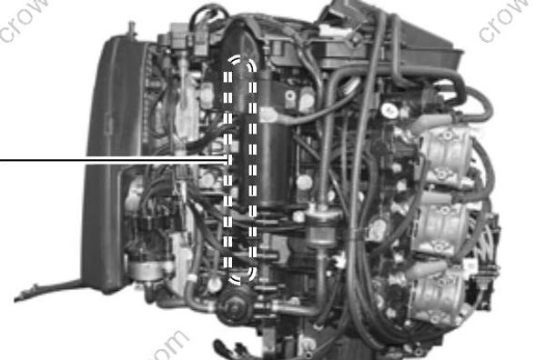
- Pressed-in fittings
The rear oil distribution manifold provides lubrication for each cylinder. Each cylinder of the cylinder/crankcase has a pressed-in fitting which is connected to an oil distribution hose.
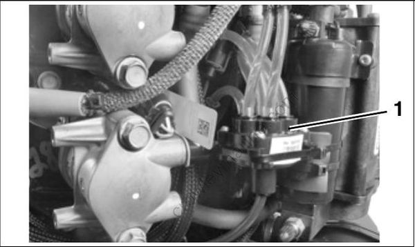
- Rear oil manifold_
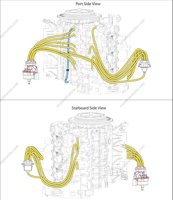
Oil Supply and Distribution Diagrams – V6

- Oil tank assembly
- Oil pick-up
- Oil supply hose
- In-line oil filter
- Oil injector assembly
- Oil distribution hoses
- Oil pressure sensor
- Rear oil manifold
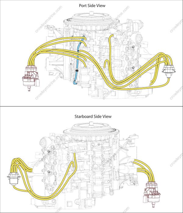
Oil Supply and Distribution Diagrams – V4

- Oil tank assembly
- Oil pick-up
- Oil supply hose
- In-line oil filter
- Oil injector assembly
- Oil distribution hoses
- Oil pressure sensor
- Rear oil manifold
Oil Recirculation System
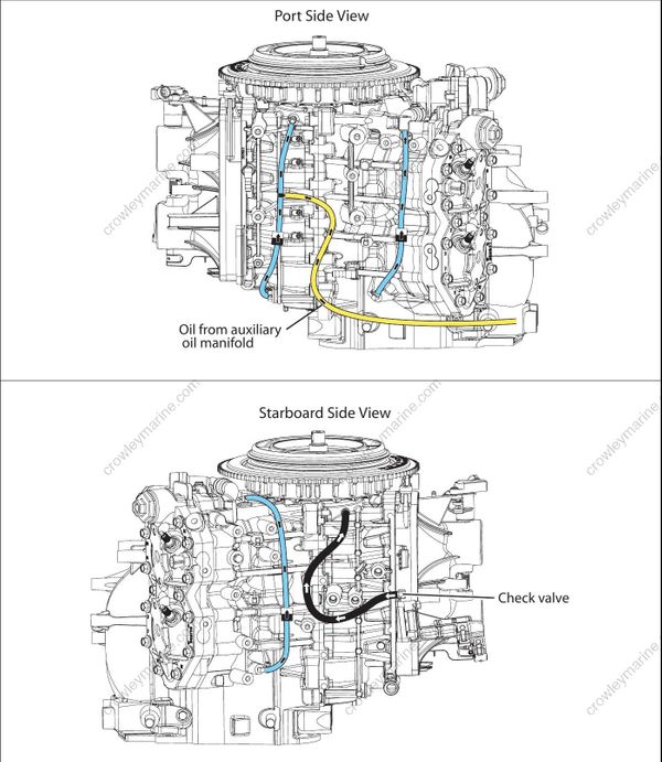
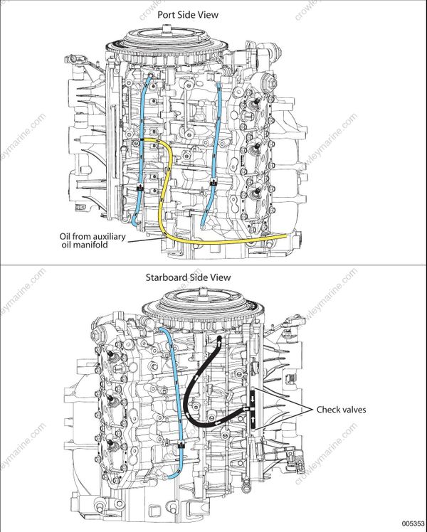
External hoses and fittings, internal cylinder/crankcase passages, and intake manifold passages are used to “recirculate” any accumulation of oil from various locations in the powerhead.
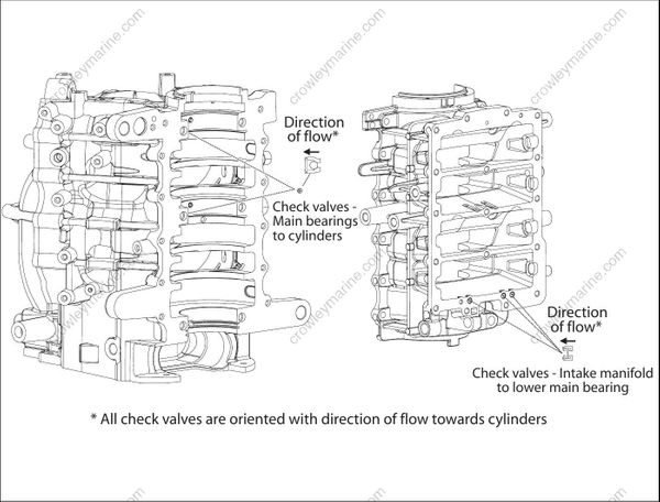
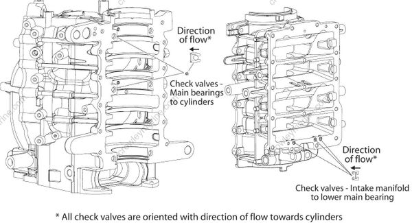
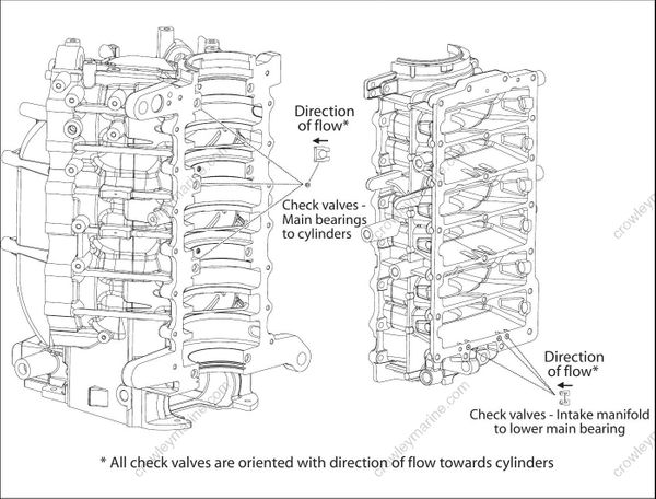
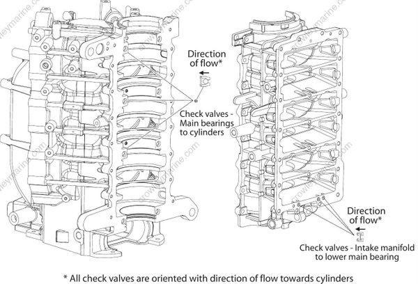
The movement of oil in these “oil circuits” is controlled by check valves
Cylinder Recirculation
Internal powerhead oil drain passages connect the intake port areas of the cylinders to circulate residual oil in the block.
External fittings and in-line check valves on each side of the cylinder block control the movement of oil from the lower cylinder port to the upper cylinder port.
Crankcase / Main Bearing Recirculation
The movement of oil through the main bearings is controlled by internal passages, external fittings and hoses, and check valves. Oil moves from the crankcase areas of the higher cylinders through grooved passages in the crankcase to the center and lower main bearings. Additional oil moves through intake manifold passages
to the crankcase and lower main bearing.
External Hoses and Check Valves
the intake port areas of the cylinders to circulate residual oil in the block.
Oil moves from the lower main bearing cavity to an external hose with in-line check valve and to External fittings and in-line check valves on each the upper main bearing. Additional oil from the side of the cylinder block control the movement of rear oil manifold is supplied to this oil circuit. oil from the lower cylinder port to the upper cylinder port.
Oil moves from Intake manifold passages to external check valve fittings and hoses and to the upper main bearing.
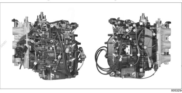
Recirculation Hose Routings and Check Valve Diagrams – V6
Recirculation Hose Routings and Check Valve Diagrams – V4