SERVICING
Removal
Raise the outboard and engage the tilt support.
Remove the blue and green wires from pump motor connector housing.
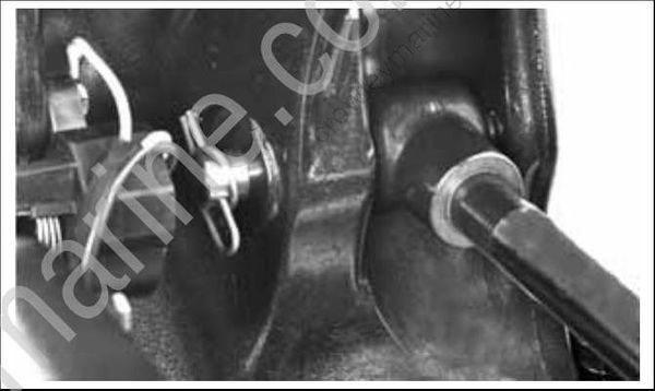
Remove the spring clip from the cylinder pin.
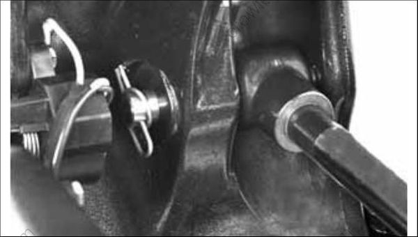
Thread Adapter, P/N 340624, onto Slide Hammer, P/N 391008. Screw the adapter into the cylinder pin and remove the pin.
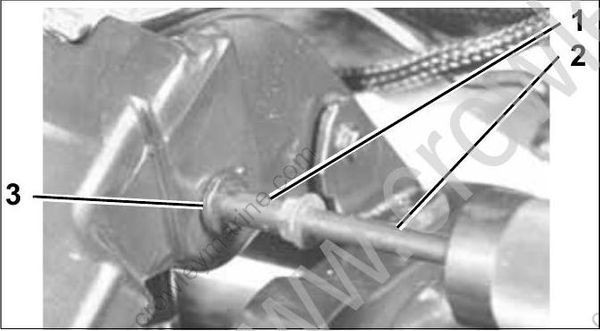
- Thread adapter
- Slide hammer
- Cylinder pin
Remove one of the 3/4 in. locknuts from the angle adjustment rod. Remove the rod from the stern brackets.
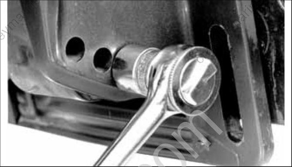
Remove the unit from the stern brackets far enough to remove the ground lead from the pump motor mounting screw.
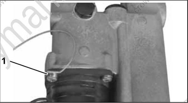
- Ground lead
Disassembly
Thoroughly clean the unit before disassembling. Scrub all outside surfaces with a stiff brush and hot, soapy water to prevent surface dirt from contaminating internal parts.
Always use a lint free shop cloth when handling power trim/tilt components.
If painting the unit is required, paint it after it is completely assembled. Painting of individual components may cause flakes of paint to enter the hydraulic passages during assembly. Tape the trim/tilt piston rods before painting.
There may be high pressure behind some power trim valves. To avoid injury when removing manual release valve, be sure to cover valve with a shop cloth until the pressure is released. Wear safety glasses.
IMPORTANT: Before removing manual release valve, relieve pressure by fully extending cylinder. Screw the manual release valve in. Remove the retaining ring using a small pick or screwdriver.
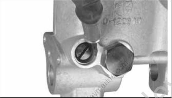
Remove the manual release valve.
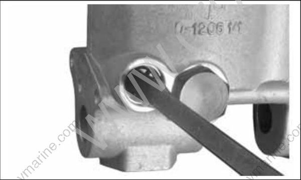
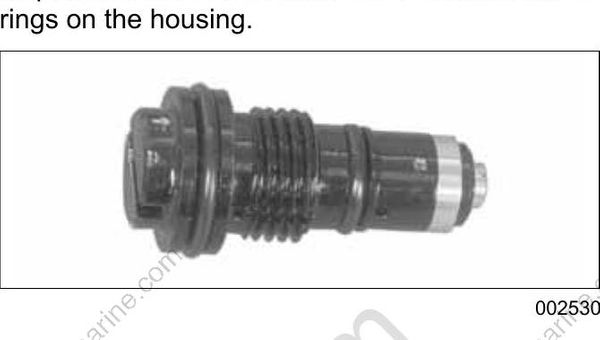
Inspect the manual release valve. Discard the O-rings on the housing.
Remove the four large motor flange retaining screws. Remove the motor and discard O-ring.
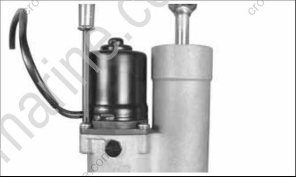
Remove drive coupler from either the motor or the pump assembly.
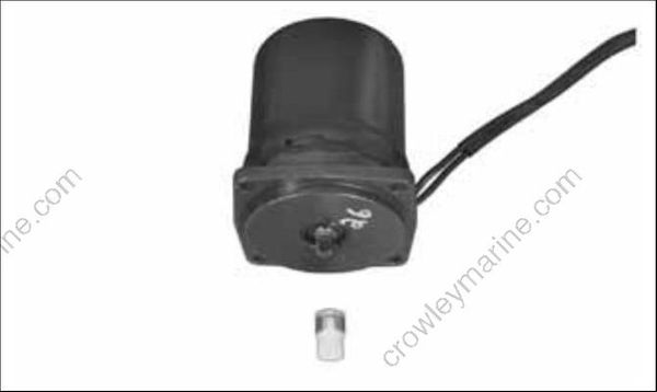
Assembly
IMPORTANT: Use only Evinrude/Johnson_ Bio degradable TNT Fluid to fill the hydraulic system.
Install drive coupler in pump assembly.
Install a new motor O-ring.
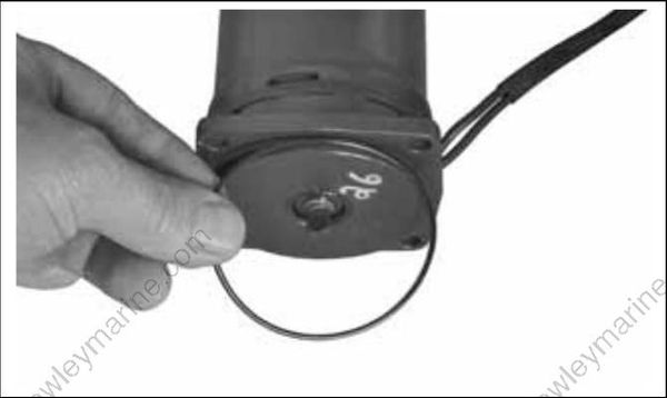
Position the motor on the manifold and install the four screws and lock washers. Tighten the screws to a torque of 35 to 52 in. lbs. (4 to 6 N•m).
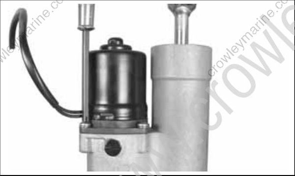
Oil O-rings and install them on the manual release valve. Oil and install the manual release valve.
Tighten the valve to a torque of 45 to 55 in. lbs. (5 to 6 N•m).
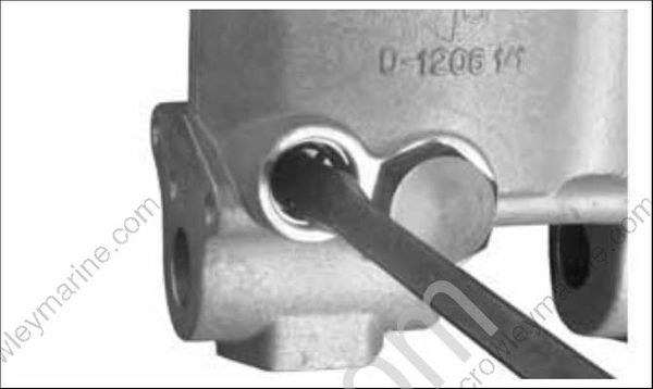
Install retaining ring in groove.
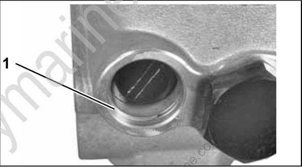
- Retaining ring
Fill the oil reservoir up to the fill plug with Evinrude/Johnson Biodegradable TNT Fluid. Install the fill plug.
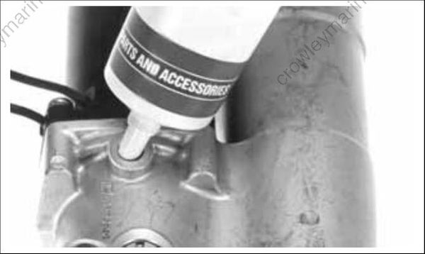
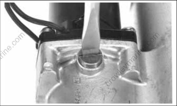
Run the motor, then recheck oil level. Cycle the unit several times and check the oil level when the cylinder is fully extended. Oil should be level with bottom of fill port. Install and tighten the fill plug to a torque of 45 to 55 in. lbs. (5 to 6 N•m).
Installation
Lubricate the cylinder and thrust rod bushings with Triple-Guard grease. Install the bushings.
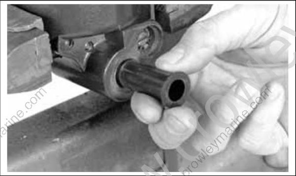
Install the ground lead. Position the hydraulic unit between the stern brackets.
Lubricate the angle adjustment rod with Triple- Guard grease. Install the rod. Tighten the locknuts to a torque of 20 to 25 ft. lbs. (27 to 34 N•m).
Connect the pump motor wires.
Lubricate the cylinder pin with Triple-Guard grease. Align the cylinder into the swivel bracket. Install the cylinder pin.
Secure the cylinder pin with cotter clip.