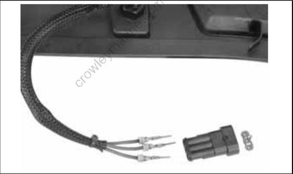
UPPER COVER SERVICE
Latch Hook Installation
Insert threaded bracket into pocket.
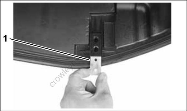
- Bracket
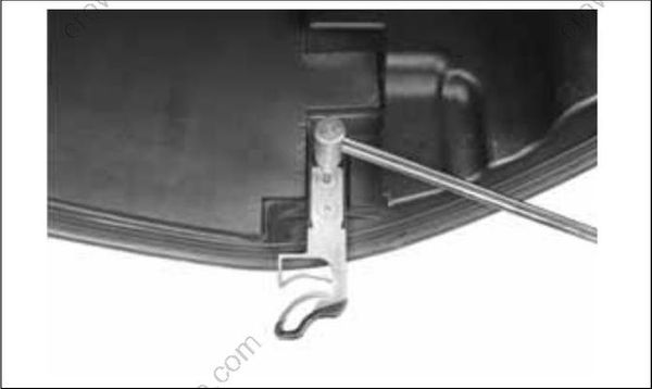
Apply Ultra-Lock to screw threads. Place hook into position with opening toward the front. Tighten screws to a torque of 60 to 84 in. lbs. (7 to 9.5 N·m).
LOWER COVER SERVICE
Lower Cover Removal
Remove lower engine cover screws.
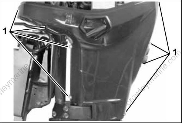
- Lower cover screws
Loosen port side cover slightly, and disconnect trim/tilt switch connector. Then, remove port and starboard covers.
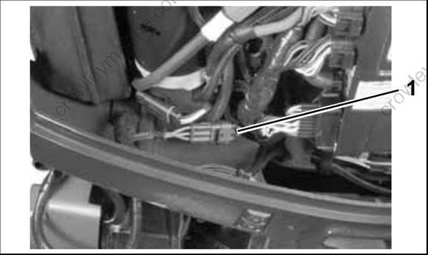
- Trim/tilt switch connector
Lower Cover Installation
Installation of lower motor covers will be easier if the following steps are performed in order:
Install air silencer on throttle body.
Place starboard cover on outboard and route fuel hose and battery cable through grommet notch.
Insert trim cable grommet into port side cover.
Connect trim/tilt switch connector.
Place port side cover into position on outboard.
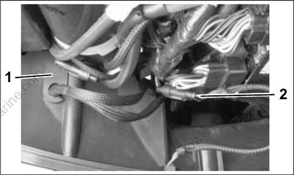
- Trim cable grommet
- Trim/tilt switch connector
Start the screw above the exhaust relief grommet first. Tighten just enough to hold the grommet in place.
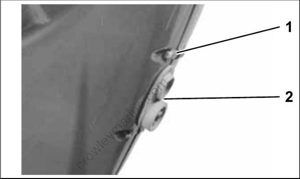
- Start this screw first
- Exhaust relief grommet
Start the top front screw next and draw cover halves together.
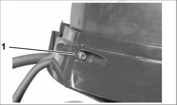
- Start this screw second
Install remaining cover screws and tighten all screws to 24 to 36 in. lbs. (3 to 4 N·m).
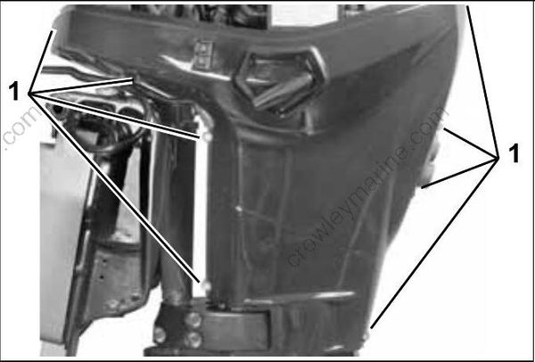
- Lower cover screws
Latch Handle Installation
Apply a light coat of Triple-Guard grease to latch handle shaft. Insert handle into lower cover.
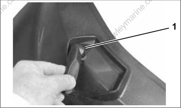
- Triple-Guard grease
Apply Ultra-Lock to screw threads. Place spring washer and hook into position and tighten screw to a torque of 180 in. lbs. (20 N·m).
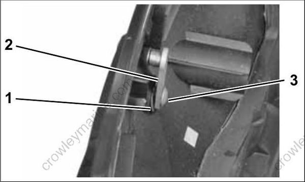
- Spring washer
- Hook
- Screw
Trim Switch Installation
Place switch into position through cover
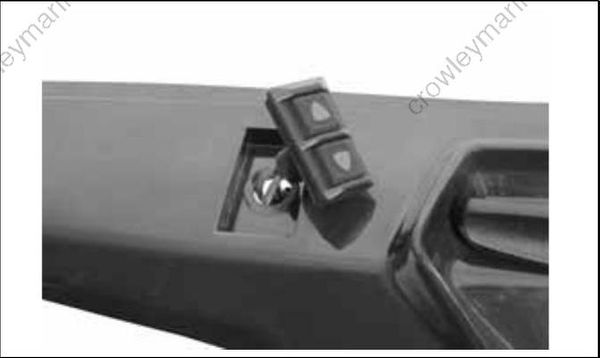
Install nut on switch. Tighten nut to a torque of 10 to 16 in. lbs. (1 to 2 N·m).
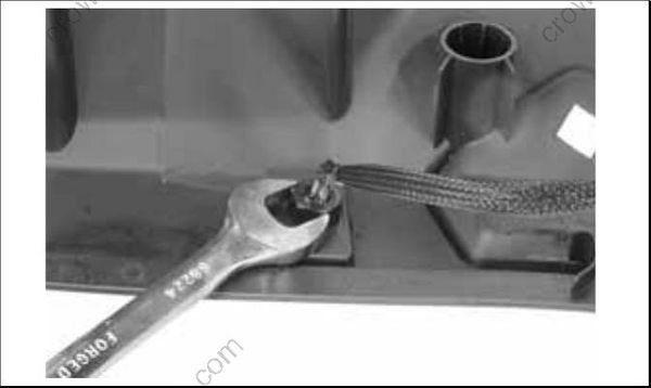
Install electrical connector. Refer to CONNECTOR SERVICING on p. 148.