

Step 1: Control Cable Identification
IMPORTANT: Control cable function must be identified before rigging outboard.
Identify each control cable:
- Put the control handle into NEUTRAL position. The throttle cable casing guide will retract completely and the shift cable casing guide will go to the midpoint of its travel.

- Shift cable casing guide extended to midpoint
- Throttle cable casing guide retracted
Extend the control cables and lubricate them with Triple-Guard grease.

Step 2: OUTBOARD INSTALLATION
Hull Preparation
Maximum Capacity
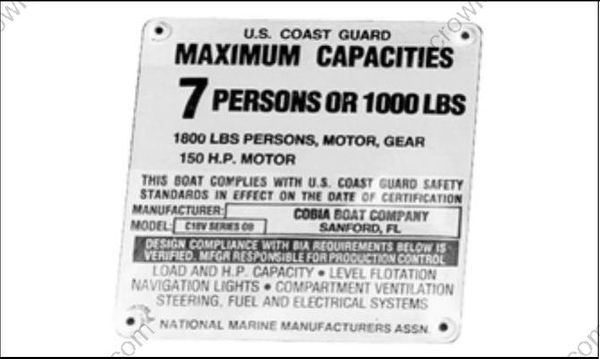
Do not overpower the boat by installing an outboard that exceeds the horsepower indicated on the boat’s capacity plate. Overpowering could result in loss of control.
Before installing outboard:
- Refer to the boat manufacturer's certification label for maximum horsepower rating.
- Refer to ABYC Standards to determine the maximum horsepower capacity for boats with out certification labeling.
Mounting Surface
Inspect transom surface prior to drilling mounting holes.
- The transom should meet ABYC Standards.
- The transom must be flat.
- The transom angle should be approximately 14 degrees.
- Check transom strength and height.
The stern brackets must contact the flat surface of the transom. Modify trim that prevents the stern brackets from resting against the transom surface. Do not modify stern brackets.
DO NOT install an outboard on a curved or irregular surface. Doing so can wear, bind, and damage components, causing loss of control.
Transom Clearances
Make sure the transom and splash well area pro vide adequate clearances:
- The top edge of the transom should be wide enough to allow full steering travel. The ABYC standard for most single outboard installations is 33 in. (84 cm).
- Check cable and hose routing clearances.
- Make sure there is clearance for mounting bolts and washers. Check the inside area of the transom for obstructions before drilling holes.
Water Flow
Inspect the hull area directly in front of the mounting location.
- Boat-mounted equipment should not create turbulence in the water flow directly in front of the outboard's gearcase. Turbulence or disruptions in the water flow directly in front of the gearcase will affect engine cooling and propeller performance.
- Avoid locating outboard centerlines within 3 in. (76 mm) of bottom strakes on dual-outboard installations.
Mounting Hardware
Use all mounting hardware supplied with the outboard to help ensure a secure installation. Substituting inferior hardware can result in loss of control.
The required outboard mounting bolts, backing plates, washers, and nuts are used to attach the outboard to the frame of the shipping pallet.
Refer to the outboard's parts catalog for alternate length mounting bolts or replacement parts.
- Use only Evinrude/Johnson Genuine Parts or parts of equivalent type, strength, and material.
- Use the mounting hardware provided with outboard whenever possible.
Transom Measuring and Drilling
Hull Centerline
Use the chines of the boat as reference points to locate the centerline of the boat transom.
Use a straightedge to draw a line connecting the port and starboard chines.
Use a framing square to accurately place a vertical line on the transom. The centerline of the hull should be in line with the keel, and perpendicular to the midpoint of the line connecting the chines.

- Chine
- Strake
- Keel
- Hull centerline
Transom Height
Make sure the transom height matches the length of the outboard to be installed.
- A 19 to 21 in. (48.3 to 53.3 cm) transom height uses a 20 in. (50.8 cm) shaft outboard.
- The shaft length of the outboard being installed should come close to matching the transom height of the boat.
Determine transom height by measuring from the top edge of the transom, along the centerline.
Use a straightedge as a reference to extend the bottom of the boat.
Position the straightedge along centerline. The distance from the top edge of the straightedge to the top edge of the transom is the actual transom height.
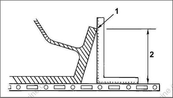
- Top edge of transom
- Actual transom height
Transom Drilling Locations
POWER TRIM MODELS
All models use the standard ABYC 4-Bolt mounting pattern.
Transom drill fixture, P/N 434367 or P/N 385368, may be used as a guide for correct hole placement. If drill fixture is unavailable, refer to Drilling and Hardware Diagrams on p. 38 for measurements.
Position drill fixture on top of transom or bracket and align indicator points with centerline.

Transom drill fixture P/N 434367 (heavy duty)
The indicators are affected by the squareness of the top edge of the transom. If either side of the fixture must be raised more than ¼ in. (6 mm) above the transom's top surface to make both indicators align, the transom must be modified.
IMPORTANT: DO NOT assume that the top edge of the transom is straight. Position the drill fixture based on measurements aligning it to the bottom of the hull.
IMPORTANT: Maintain at least 1.75 in. (45 mm) of transom surface above the top mounting bolts.
Before drilling any mounting holes:
- Make sure the hole locations provide enough clearance for mounting bolts and washers.
- Check the inside area of the transom for obstructions.
- Check transom height(s) at centerlines.
Drill four ½ in. (13 mm) mounting holes in the appropriate locations.
IMPORTANT: Be sure to drill the required holes perpendicular to transom surface.
MANUAL TILT MODELS
Center the outboard on the transom (or mounting bracket) and tighten clamp screws by hand.
Use each stern bracket’s mounting holes as a guide to drill holes through the transom.
- 25–30 HP models require two 11/32 in. (8.7 mm) holes.

Drilling and Hardware Diagrams
POWER TRIM MODELS
IMPORTANT: This is not a template.

- Center of Transom
- Top of Transom
- 1/2” Bolt Hole Locations
- Outside of Transom
- Bolt *
- 318272 Plate
- 318273 Retainer
- 319886 Screw
- 307238 Washer
- 320248 Washer
- 313623 Nut
- 318572 Cap
Quantity
4
2
2
4
2
4
4
4
*Choose from the following bolt sizes:
327053 3 in. (76 mm)
318573 3 1/2 in. (89 mm)
313327 4 in. (102 mm)
336676 4 1/2 in. (114 mm)
331578 5 in. (127 mm)
321577 6 in. (152 mm)
MANUAL TILT MODELS
IMPORTANT: This is not a template.

- Center of Transom
- Top of Transom
- 11/32” Bolt Hole Locations
Lifting the Outboard
Lifting Fixtures
To avoid personal injury, make sure the lifting capacity of the hoist is at least twice the weight of the outboard.
DO NOT allow the lift hook or chain from the hoist to come in contact with any part of the engine during lifting.
Open the shipping carton and remove packing material from top of carton.
Install Lifting Tool, P/N 354717, on both sides of the tilt tube.
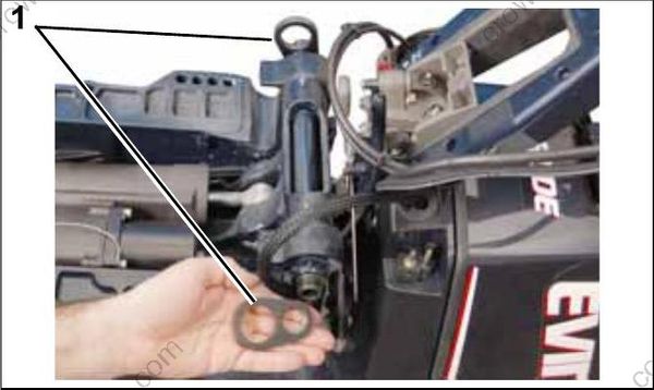
- Lifting tool, P/N 354717
To avoid personal injury or outboard damage, be sure the lifting tool is fully threaded on both sides of the tilt tube.
Use an appropriate chain, at least 36 inches (91 mm) long with two snap hooks, each capable of lifting 500 lbs. (227 kg).
Attach hooks to lifting device and attach chain to hoist.
Use this tool for horizontal lifting of 30 HP and smaller Evinrude E-TEC models ONLY.
DO NOT use this tool to lift outboards larger than 30 HP Evinrude E-TEC models.
To avoid personal injury and boat or outboard damage, DO NOT use this tool to install or remove outboard from transom as outboard can unexpectedly tip.
Lift the engine out of the carton.

- Lifting tool, P/N 354717
Remove upper motor cover.
Place clean pad or cardboard on the floor.
Lower outboard onto the pad. Use hoist to carefully roll the outboard onto its port side.
To avoid damage to the outboard, DO NOT allow the outboard to fall unrestrained.

Remove chain from lifting tool.
Remove lifting tool from outboard.
Attach chain to lift eye on back of engine block.
If the chain snap hooks are too large, the cast in lift eye could break causing the outboard to drop suddenly causing personal injury and damaging the outboard.

- Lift eye
Carefully lift engine with hoist.
To avoid damage to the outboard, lift the outboard in one smooth motion. DO NOT allow the outboard to bounce.

Steering Systems
Mechanical Cables
All Evinrude outboards equipped with tilt tubes are designed to be compatible with mechanical steering systems that meet ABYC Standard P-17.
Extend the steering cable and lubricate the inner core before installation.
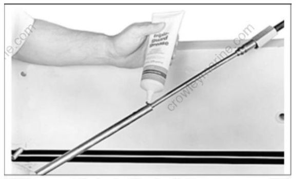
ABYC-approved Mechanical Steering Cable
IMPORTANT: Install steering cable through tilt tube before mounting outboard on transom. Tighten nut securely.
Drag Links
Use Steering Connector Kit, P/N 173699, to allow full steering travel:
Install cable wiper nut on tilt tube and connect drag link to the correct location on the steering arm. For single engine, single cable applications, the drag link should be installed in the rear hole.

- Drag link connection
- Wiper nut
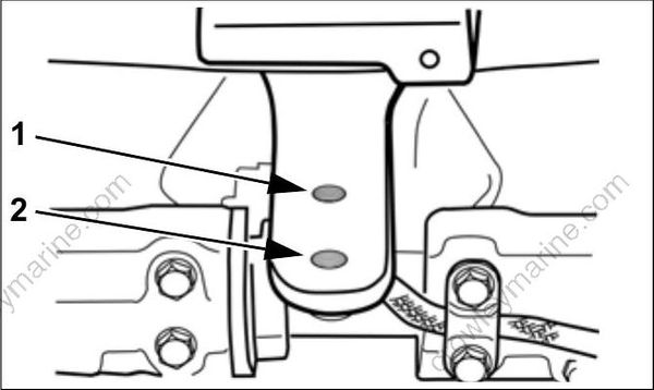
- Rear Location –Steering drag link connection
- Front Location –Bar connection (multiple outboard installations)
Outboard Mounting
IMPORTANT: Some rigging components, such as steering cables, must be fitted to the outboard before the outboard is mounted to the transom. Determine what equipment will be installed before mounting.
Mounting Height
Boat performance depends on outboard mounting height.
Generally, the anti-ventilation plate of the gear case should align with the bottom of the hull. Conventional V-hulls often perform well with the anti-ventilation plate approximately 1 in. (25 mm) above the bottom of the hull.
Boats that exceed 50 MPH may benefit from higher outboard heights. Consult the boat manufacturer for specific outboard mounting height information for a particular hull.
Test outboard and boat performance at different heights until the best performance is achieved.
IMPORTANT: Be sure that outboard water pressure is not adversely affected by the mounting height of the outboard.
Mounting Bolt Installation
IMPORTANT: Use a marine sealant rated for above or below waterline use. RTV silicone is not approved for below waterline use. Polyurethane sealants are not easily removed and may damage outboard or boat mounting surfaces.
Apply marine sealer under hex heads of bolts, on the mounting plates, and to the bolt shanks.

POWER TRIM MODELS
Assemble transom mounting plates on mounting bolts.
Install the mounting bolts through the transom from the inside of the boat.

Position the square aluminum transom mounting plates (when applicable) so the retainer holes are horizontal.
Position hex head of bolt with flats toward holes in the mounting plates. Install retainer over hex head of the bolt and secure it with screws provided.
Install all washers and nuts. Tighten to a torque of 40 ft. lbs. (54 N·m).
If either side of the transom deforms or cracks when the bolts are tightened to their recommended torque, the transom construction may not be adequate or may be deteriorated. Structural failure of the transom could result in loss of boat control and injury to the occupants.
MANUAL TILT MODELS
Install the mounting bolts through the stern brackets and transom. Install round backing plates and locknuts onto bolts and tighten securely.

- Round backing plates
- Locknuts
