

GEARCASE
Install the port and starboard water intake screens with water intake holes positioned at the rear of gearcase. Tighten screws to a torque of 10 to 14 in. lbs. (1.1 to 1.6 N·m).

- Water intake screen
To prevent loss of operator control, check for proper shifting operation and adjust, if necessary.
IMPORTANT: During break-in period of a reassembled gearcase, change the gearcase lubricant between 10 to 20 hours of operation.
WATER PUMP SERVICE
Disassembly
Remove the impeller housing screws.

- Screws
Pull up on the driveshaft and remove the drive shaft with the water pump assembly from the gearcase. Remove the water pump assembly from the driveshaft.
Remove the impeller plate and gasket. Discard the gasket.
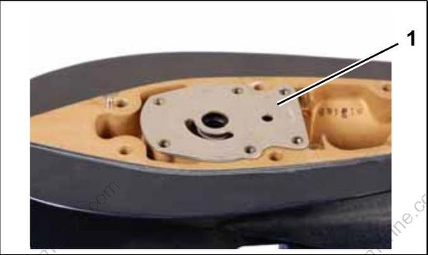
- Impeller plate
Remove the water pump grommet, all O-rings, and the shift rod bushing from the impeller housing.
Inspection
Check impeller for overheating, hub separation, and other wear or damage.
Check liner and wear plate for scoring, distortion, and impeller material transfer.
Inspect the housing for cracks or melting.
Assembly
Oil and install the shift rod bushing into the impeller housing.

- Shift rod bushing
Apply Triple-Guard grease to the shift rod O-ring and install below bushing.
Apply a thin bead of Adhesive 847 in the inner groove of the impeller housing and install a new impeller cup O-ring.

- Shift rod O-ring
- Impeller cup O-ring
Lightly coat the exterior of the impeller cup with Gasket Sealing Compound. Align tabs of impeller cup with location holes of impeller housing and install the impeller cup into the impeller housing.

- Tabs, impeller cup
- Location holes
Lightly coat the inside of the impeller cup with oil. With a counterclockwise rotation, install the impeller into the impeller cup.
IMPORTANT: The sharp edge of cam slot in the impeller is the leading edge during rotation.

- Impeller
- Sharp edge
Apply Adhesive 847 to the outer seal groove of the impeller housing. Install a new seal into the groove.
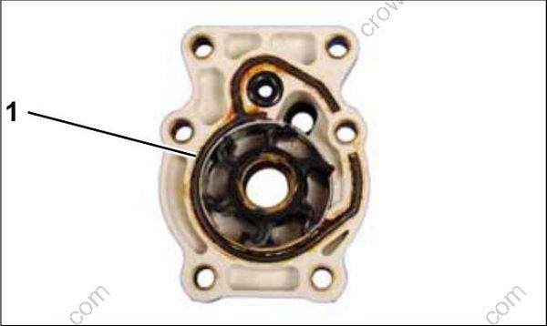
- Seal
Lightly oil pinion splines of the driveshaft. Slide the driveshaft through the impeller housing and impeller until drive cam flat of the driveshaft is below the impeller. Align drive cam flat with groove of the impeller. Install the impeller drive cam.
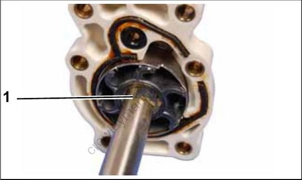
- Drive cam
Sharp edge of the cam is leading edge during driveshaft rotation. Slide the impeller housing down the driveshaft. Engage the impeller with the cam.
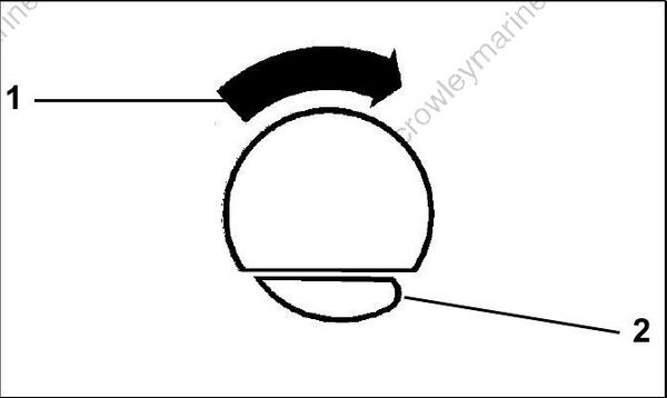
- Driveshaft rotation
- Drive cam
IMPORTANT: Make sure the impeller is oriented properly and engages the impeller cam properly. Serious powerhead damage will result if impeller cam is displaced.
Lightly coat both sides of a new impeller plate gasket with Gasket Sealing Compound. Place gasket on the gearcase.
Place the impeller plate over the gasket.
Slide the driveshaft down into the gearcase and engage the pinion.
Turn the driveshaft until holes of the impeller housing are aligned with holes of the gearcase. Apply Gasket Sealing Compound to threads of the impeller housing screws. Tighten the screws to a torque of 60 to 84 in. lbs. (7 to 9.5 N·m).

Apply Adhesive 847 to outside of water tube grommet. Install grommet and locate grommet bosses into holes of impeller housing.
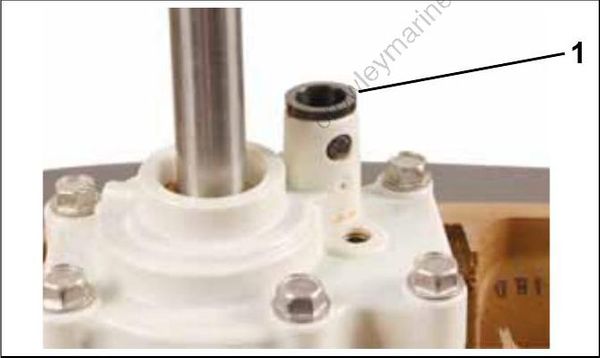
- Grommet
GEARCASE DISASSEMBLY
Wear safety glasses to avoid personal injury, and set compressed air pressure to less than 25 psi (172 kPa).
IMPORTANT: Clean and inspect all parts during disassembly. Replace any damaged parts, seals, O-rings, and gaskets.
Before disassembling the gearcase, examine the following:
- Gearcase Housing — Check for visible damage to skeg, strut, anti-ventilation plate, bullet, and mating surface. Check seal areas for visible signs of lubricant leakage.
- Propeller Shaft—Check for bent or damaged shaft. Check for twisted splines and damaged threads.
- Shift Rod —Check for bent, or binding rod.
- Hydrostatic Seal Grooves — Must be in good condition to help prevent propeller ventilation.
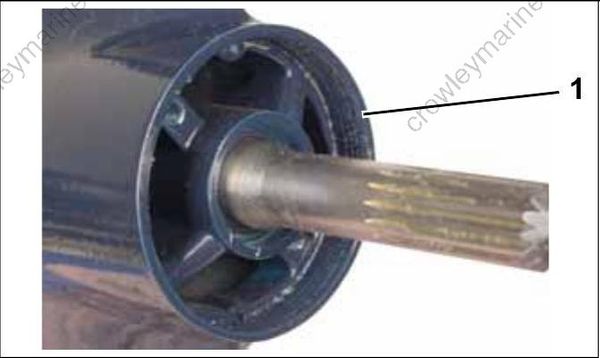
- Hydrostatic seal grooves
