

Key Switch Test
Refer to Wiring Diagrams at back of manual.
Use an ohmmeter or a continuity light to test key switch operation. Replace switch if results are incorrect with any of the following tests.
IMPORTANT: Disconnect battery and key switch wiring before proceeding with the following tests.
Stop/Ground Terminals (M)– Connect meter between the two “M” terminals. Meter must indicate NO continuity at START or ON.
Turn key switch OFF. Meter must indicate continuity.
Accessory Terminal (A) – Make sure the key switch is OFF. Connect the ohmmeter or continuity light between terminals “B” (battery) and “A” (accessory) of key switch. Meter must indicate NO continuity.
Turn switch ON. Meter must indicate continuity.
Turn key switch to START. Meter must continue to indicate continuity.
Starter Terminal (S)– Hold key switch at START. Connect meter between terminal “B” and terminal “S.” Meter should indicate continuity.
IMPORTANT: The choke function or terminal “C” of the key switch is NOT used.
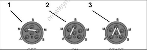
1.OFF
2.ON
3.START
Neutral Start Circuit Test
Use an ohmmeter or continuity light to test the continuity of the circuit while positioning the remote control in NEUTRAL, FORWARD, and REVERSE.
IMPORTANT: Turn propeller shaft or disconnect shift cable to allow proper remote control shift action while outboard is not running. Disconnect the instrument harness connector from the key switch harness connector.
Make sure the remote control handle is in NEU TRAL. Connect meter between terminal 5 (red/purple wire) and terminal 2 (yellow/red wire). Turn the key switch to START. Meter must indicate continuity.
Move the remote control handle to FORWARD and turn the key switch to START. Meter must NOT indicate continuity.
Move the remote control handle to REVERSE and turn the key switch to START. Meter must NOT indicate continuity.
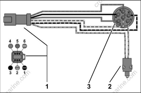
- Key switch harness connector
- Neutral start switch
- Key switch
IMPORTANT: Reconnect shift cable and instrument harness connector to key switch harness connector.
Neutral Start Switch Test
Use an ohmmeter or a continuity light to test neutral start switch operation.
IMPORTANT: All wiring must be disconnected from the switch before proceeding with this test.
Disassemble the remote control and remove the neutral start switch.
Connect one meter lead to each terminal of the switch.
- Meter must indicate continuity when the plunger is depressed
- Meter must indicate no continuity when the plunger is released.
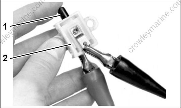
TYPICAL1.Plunger
2.Neutral start switch
Replace switch if results are incorrect.
Emergency Stop Switch Test
This switch can be part of the key switch or installed as a separate switch. Either style connects the “M” terminals of the key switch.
The emergency stop switch function grounds the stop circuit wire (black/yellow) when the lanyard clip is removed. One “M” terminal is the ground wire (black) and one “M” terminal is the stop circuit wire (black/yellow).
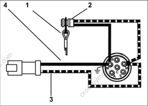
- Lanyard and clip assembly
- Emergency stop switch, separate from key switch
- Stop circuit wire (black/yellow)
- Ground wire (black)
Install the clip on the emergency stop switch or key switch. Start the outboard. Pull the clip from the switch. The outboard must stop running.
