

Start Circuit Diagram

- Marine battery
- RED wire (POS)
- BLACK wire (NEG)
- Starter solenoid
- Fuse (10 amp)
- RED/PURPLE wire
- Key switch connectors
- Ignition switch
- PURPLE wire (switched B+)
- Battery charge module connector
- Engine Management Module (EMM)
- YELLOW/RED wire, start
- BLACK wire, start signal ground
- Neutral Safety Switch (remote control)
- RED starter motor cable
- Electric starter motor
Start Circuit Operation
The starter must engage and turn the flywheel. The outboard must crank a minimum of 300 RPM to start.
Starter performance depends on the following:
- Proper battery and cable capacity.
- Clean, tight cable connections.
- Solenoid activation through the key switch and neutral safety switch.
Refer to Battery Installation on p. 25 for battery, terminal, and cable requirements.
Solenoid Wiring
The positive (B+) battery cable connects to a large terminal of the starter solenoid. This terminal also provides the 12 V power supply to the engine harness (red wire) and the 10 A fuse. The red/purple wire from the fuse holder (10 A) provides 12 V to terminal “B” of key switch.
The negative (B–) battery cable connects to the main ground stud on the starter housing.
Engine Wire Harness
Contains the following circuits:
Red/purple output wire from fuse provides 12 V to instrument harness.
Purple wire provides switched 12 V to EMM.
Yellow/red wire provides switched 12 V to solenoid (terminal “A”).
Black wire provides ground (NEG) to starter solenoid (terminal “B”).
Instrument Wire Harness
Contains the following circuits:
- Red/purple wire provides 12 V to key switch terminal “B”.
- Purple wire provides switched 12 V to engine wire harness.
- Yellow/red wire from terminal “S” of key switch provides switched 12 V to solenoid (terminal “A”) (key switch in START position).
Key Switch, ON position
12 V is applied to the accessory circuit. Key switch ON:
- Switches 12 V to terminal “A” of key switch and to the purple wires of the wire harnesses.
- Provides 12 V input to terminal 3 of EMM J1-A connector. EMM turns ON.

- Key switch, ON position – Continuity between terminals “B” and “A”
- Terminal “B”, 12 V (Red/purple)
- Terminal “A”, 12 V (Purple)
Key Switch, START Position
Key switch START:
- Switches 12 V to terminal “S” of key switch and to the neutral safety switch (in remote control).
- A closed neutral safety switch provides 12 V to the engine wire harness yellow/red wire and solenoid (terminal “A”).

- Ignition switch, START position – Continuity between terminals “B” and “A”; “B” and “S”
- Terminal “S”, 12 V
- Neutral safety switch
ELECTRIC START TESTS
Starter Solenoid Test
Disconnect the B+ (POS) battery cable at the battery.
IMPORTANT: Disconnect all wiring from solenoid terminals before proceeding with this test. Use a digital multimeter to measure resistance.
Put one meter lead on the starter positive (+) cable terminal and the other lead on the battery positive (+) cable terminal:
- Meter must not show continuity (high reading).
- If meter shows continuity (low reading), replace the solenoid.
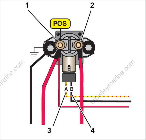
- Battery positive cable (B+) terminal
- Starter positive (+) cable terminal
- “A” terminal (yellow/red)
- “B” terminal (black)
Apply B+ to terminal “A” of solenoid and ground (NEG) to terminal “B” of solenoid. Measure resistance between the starter positive (+) cable terminal and the positive battery (+) cable terminal.
- The solenoid must close with an audible click.
- Meter must show continuity (low reading).
- If meter shows no continuity (high reading), replace the solenoid.
