

Exhaust Housing Removal
Before removing the midsection:
• Remove the gearcase. Refer to Gearcase GEARCASE REMOVAL AND INSTALLATION on p. 287.
• Remove the powerhead. Refer to POWERHEAD REMOVAL on p. 221.
Remove and discard four lower mount screws.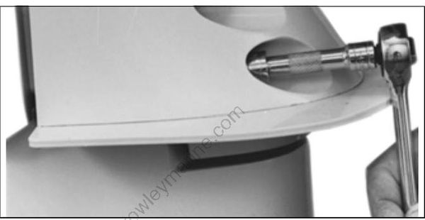
32590
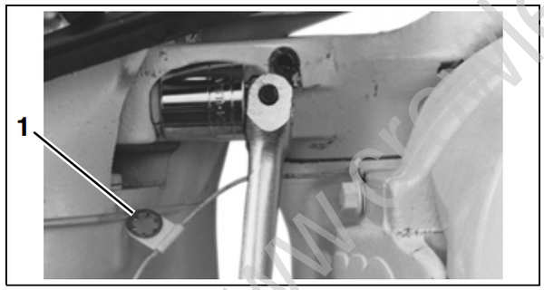
Remove the steering arm ground lead and screw.
Remove two upper mount screws.
32589
- Ground lead (removed)
Remove the exhaust housing.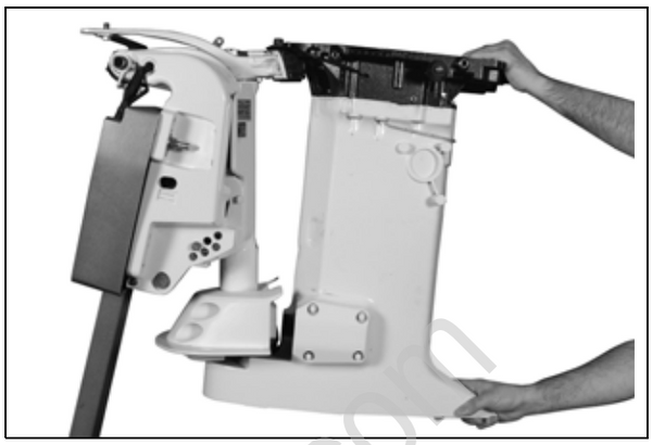
006979
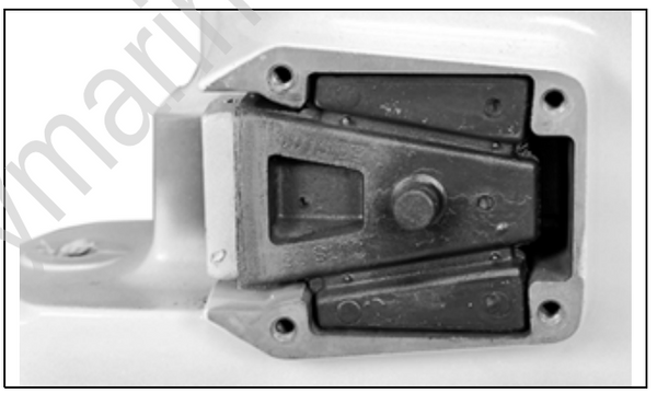
Remove lower mount covers and inspect the lower mounts.
23033
TYPICAL
If replacement is necessary, lubricate mount with soapy water and carefully pry at both ends to remove.
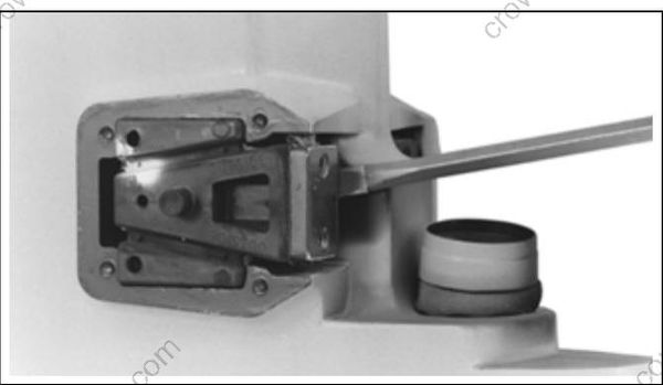
32578
Exhaust Housing Disassembly – 3.3 L models
Remove two front adapter to outer exhaust housing screws. Remove three nuts at rear of the adapter.
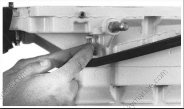
32580
Loosen and remove the upper mount plate screws and remove the mount plate.
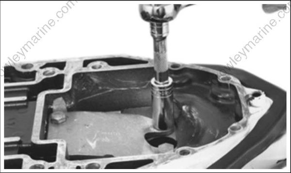
32588
Lubricate the upper mount with soapy water and pry up to remove it from the adapter housing.
Lift the adapter/inner exhaust housing out of the exhaust housing.
Mark the water tube for correct reassembly location. Remove six inner exhaust housing screws.
Remove the inner exhaust housing..
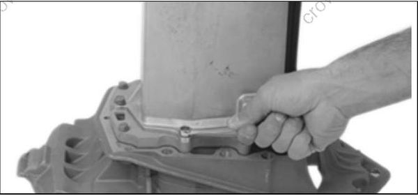
13638
Remove the water tube and grommet from the inner exhaust housing. Discard the grommet.
Loosen retaining screws and remove the cover from water plate.
Loosen retaining screws and remove water plate from the adapter.
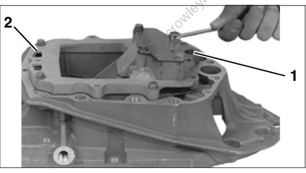
13641
- Cover
- Water plate
Exhaust Housing Disassembly – 3.4 L models
Remove two front adapter to outer exhaust housing screws.
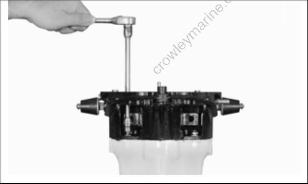
006980
Remove three nuts at rear of the adapter.
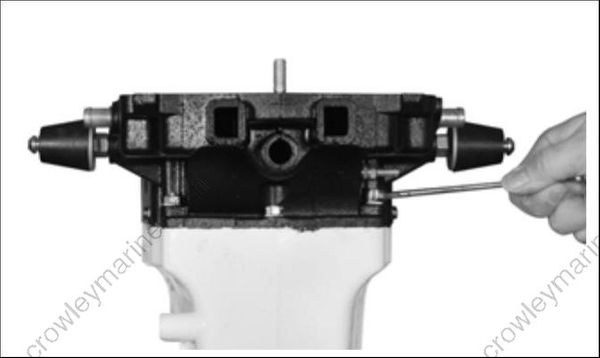
006978
Loosen and remove the upper mount plate screws and remove the mount plate.
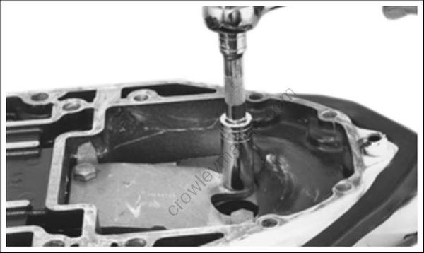
32588
Lubricate the upper mount with soapy water and pry up to remove it from the adapter housing.
Lift the adapter/inner exhaust housing out of the exhaust housing.
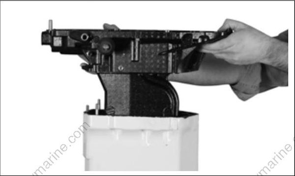
006981
Cleaning and Inspection
Wear safety glasses to avoid personal injury, and set compressed air to less than 25 psi (172 kPa).
Clean all parts with parts cleaning solvent and drywith compressed air. All nut and screw threads coated with thread locking material must be thoroughly cleaned before assembly. When using athread locking product, be sure to prime the threads with Locquic Primer.
Examine the upper and lower thrust mounts, and replace if deteriorated or damaged.
Before checking the exhaust housing for distortion, thoroughly clean the top and bottom mating surfaces and remove all sealer and corrosion.
Check the exhaust housing for distortion. Place the housing on a surface plate. Using a dial indicator, check flatness by measuring the run-out on the top edge of housing. The maximum allowablerun-out is 0.009 in. (0.228 mm). If you do not have access to a dial indicator and surface plate, seek the services of a machine shop. DO NOT attempt to straighten a distorted housing. Replace it.
IMPORTANT: A distorted exhaust housing will cause the upper driveshaft splines to wear excessively and will damage the crankshaft splines.
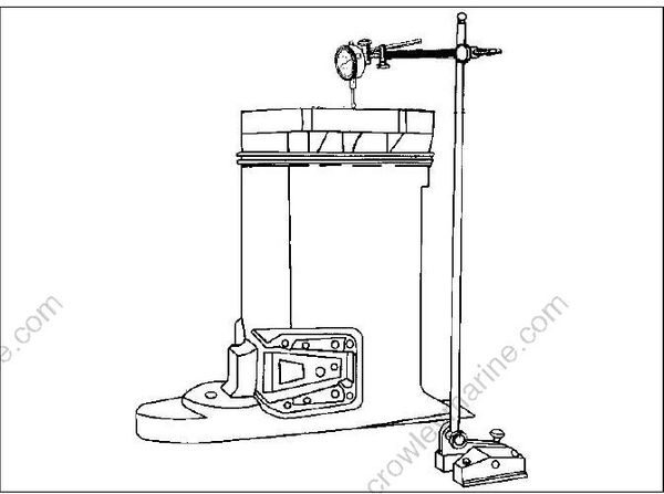
DR2223
Inspect the water tube for obstructions or kinks, which may restrict water flow.
Exhaust Housing Assembly – 3.3 L models
Lightly coat both sides of a new gasket with Gasket Sealing Compound and install the gasket and water plate.
Apply Gasket Sealing Compound to threads of the water plate retaining screws. Install with washers and tighten to a torque of 60 to 84 in. lbs. (7 to 9.5 N·m).
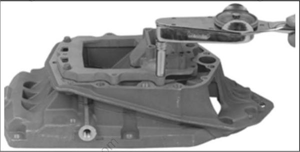
13644
Apply Adhesive 847 to the water plate surface, then place the cover on the water plate.
Apply Gasket Sealing Compound to threads of cover retaining screws. Install with washers andtighten to a torque of 60 to 84 in. lbs. (7 to 9.5N·m).
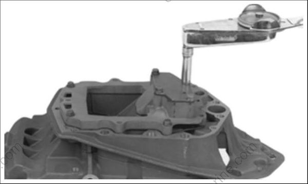
13642
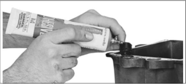
Coat the outside diameter of a new water tube grommet with Adhesive 847. Install grommet in the inner exhaust housing. Install the water tube
7715
Lightly coat both sides of a new inner exhaust housing gasket with Gasket Sealing Compound and install it.
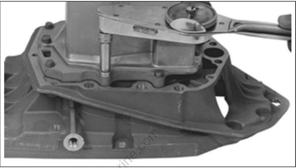
Install the inner exhaust housing. Coat inner exhaust housing screws with Gasket Sealing Compound and tighten to a torque of 60 to 84 in. lbs. (7 to 9.5 N·m).
13639
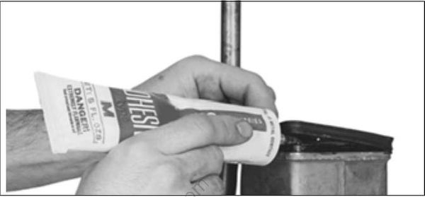
Apply Adhesive 847 to the bottom flange of the inner exhaust housing. Install a new seal. Apply Triple-Guard grease to outer seal surface.
7713
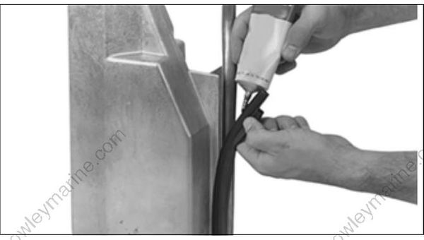
Install a new inner exhaust housing seal. Apply Adhesive 847 to the seal groove.
13640
Clean and degrease the adapter housing and outer exhaust housing mating surfaces with Cleaning Solvent. Apply Gel-Seal II sealant to the adapter flange of the exhaust housing.
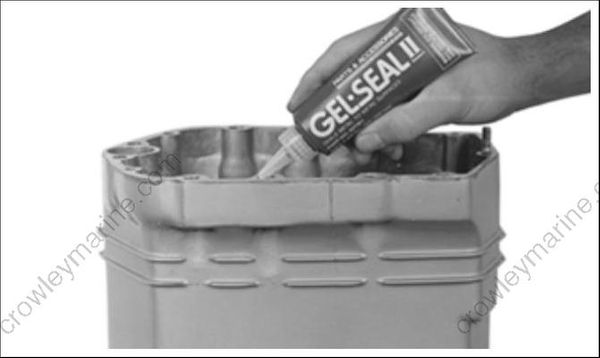
13692
Place the adapter/inner exhaust housing into the exhaust housing. Align the water tube.
Loosely install the small retaining screws, nuts, and washers.
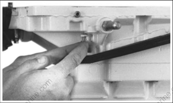
32580
Lubricate the upper mount with soapy water and push into place in the adapter housing. The mount radius must face aft with the “TOP” mark facing up.
Apply Locquic Primer and Nut Lock to the upper mount plate screws and install the plate and screws loosely. Install the ground lead and star washer under the forward starboard screw.
Align the outer exhaust housing and adapter by placing two powerhead mounting screws through their holes.
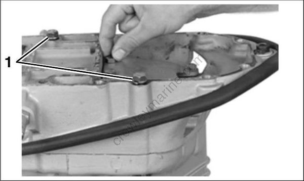
13689
- Powerhead mounting screws
Install four mount plate screws and washers and tighten to a torque of 22 to 24 ft. lbs. (30 to 33N·m).
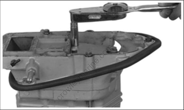
13690
Tighten the small adapter to exhaust housing screws and nuts to a torque of 60 to 84 in. lbs. (7 to 9.5 N·m).

13691
If removed, coat the lower mounts with soapy water and press into the exhaust housing with the “OUTSIDE” mark facing outward.
Install the mount covers. Apply Nut Lock to screws, install washers and screws, and tighten to a torque of 156 to 180 in. lbs. (18 to 20 N·m).
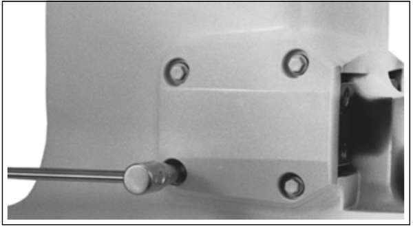
32579
Exhaust Housing Assembly – 3.4 L models
Apply Adhesive 847 to the bottom flange of the inner exhaust housing. Install a new seal. Apply Triple-Guard grease to outer seal surface.
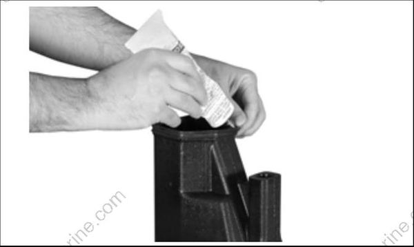
006984
Install grommet and water tube in the inner exhaust housing.

006982
- Water tube grommet
Clean and degrease the adapter housing and outer exhaust housing mating surfaces with Cleaning Solvent. Apply Gel-Seal II sealant to the adapter flange of the exhaust housing.

13692
Place the adapter/inner exhaust housing into the exhaust housing. Guide the water tube through the hole in the outer housing.
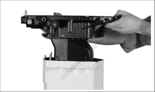
006981
Loosely install the small retaining screws, nuts, and washers.
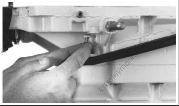
32580
Lubricate the upper mount with soapy water and push into place in the adapter housing. The mount radius must face aft with the “TOP” mark facing up.
Apply Locquic Primer and Nut Lock to the upper mount plate screws and install the plate and screws loosely. Install the ground lead and star washer under the forward starboard screw.
Align the outer exhaust housing and adapter by placing two powerhead mounting screws through their holes.

006985
- Powerhead mounting screws
Install four mount plate screws and washers and tighten to a torque of 22 to 24 ft. lbs. (30 to 33 N·m).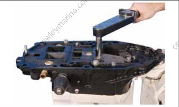
006986
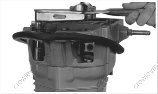
Tighten the small adapter to exhaust housingscrews and nuts to a torque of 60 to 84 in. lbs. (7 to 9.5 N·m).
13691
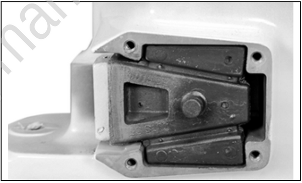
If removed, coat the lower mounts with soapy water and press into the exhaust housing with the “OUTSIDE” mark facing outward.
23033
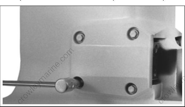
Install the mount covers. Apply Nut Lock to screws, install washers and screws, and tighten to a torque of 156 to 180 in. lbs. (18 to 20 N·m).
32579
Exhaust Housing Installation
Bring the exhaust housing into position with the stern bracket.
Install four new lower mount screws with lockpatch. Tighten screws to a torque of 38 to 45 ft. lbs. (51 to 61 N·m).
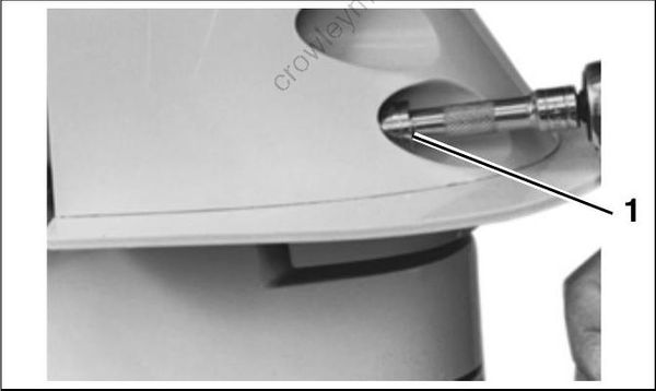
- Lower mount screws
Apply Ultra Lock to upper mount screws and tighten to a torque of 64 to 72 ft. lbs. (87 to 98 N·m).
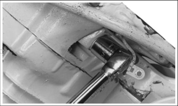
7716
Attach the ground lead and star washer to the steering arm’s starboard side.
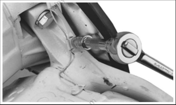
32586
If necessary, replace the exhaust adapter to lower engine cover seal. Attach with Adhesive 847.
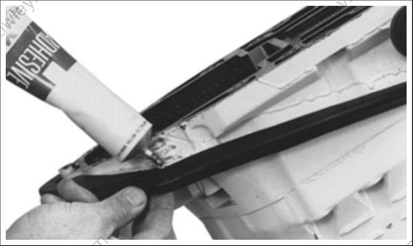
32585
Install gearcase. Refer to Gearcase GEARCASE REMOVAL AND INSTALLATION on p. 287.
Install powerhead. Refer to POWERHEAD INSTALLATION on p. 243.
