

Oil Control Settings
Oil Priming
The oiling system of the outboard must be primed:
• When the outboard is first installed.
• Whenever the oil supply to the oil lift pump is disconnected or disrupted.
• Whenever an oiling system component is removed or replaced.
Refer to Oil Supply Priming on p. 70.
Oiling Rates
EMM programming controls the rate of oil injection based on engine RPM. This rate can be adjusted for the grade of oil being used, and also for powerhead break-in. Use Evinrude Diagnostics software to access these features.
Refer to Oil Injection Rate on p. 69.
Break-in Oiling
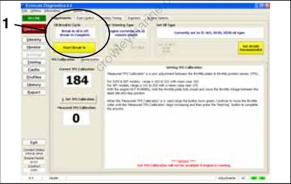
The EMM automatically supplies extra oil to the engine during the first five hours of operation, above 2000 RPM.
• Use Evinrude Diagnostics software to make sure the break-in program has been started on a new outboard.
• Use the diagnostics software to start break-in oiling after a powerhead rebuild.
008108
IMPORTANT: The operator must monitor the oil tank level to confirm oil consumption. This may require several hours of operation above idle.
OILING SYSTEM TESTS
IMPORTANT: Always perform visual inspections to identify oiling system leaks. Make sure the oil tank is filled and oil supply is not contaminated.
Oil Injection Pump Static Test
IMPORTANT: Static tests are performed with the outboard not running.
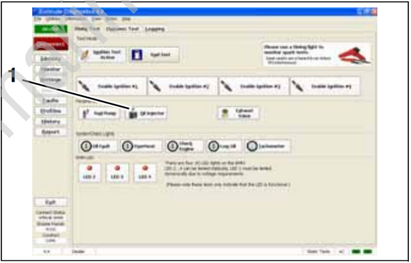
Use Evinrude Diagnostics software to activate the Oil Injector test. This test starts the EMM control function for the oil injection pump.
The EMM controls the pump by providing ground through pin 23 (blue wire) of the J1-B connector and pin 2 (blue wire) of the oil tank connector.
008116
Static Tests Screen
- Oil injector test button
IMPORTANT: This test is operating the pump with 30 V on the system voltage (55 V) circuit. The start assist circuit (SAC) of the EMM converts battery voltage (12 V) to 30 V of system voltage. Battery must be fully charged and connections must be clean and tight. Pump activation should be carefully confirmed.
Use an inductive timing light to monitor current flow through the ground circuit (blue wire) at the oil tank connector (pin 2).
If the light flashes, the EMM and oil injection circuits are not at fault.
Refer to Oil Injection Pump Voltage Test on p. 220.
Oil Injection Pump Voltage Test
Check voltage at pin 1 (white/red wire) of oil tank electrical connector.
Acceptable voltage readings:
• Key switch ON: approximately 30 V
• Outboard running: 55 V
Results:
• If voltage is not within range, refer to Oil Injection Pump Circuit Resistance Test on p. 220.
• No voltage reading, refer to System Voltage Test on p. 130.
Monitor the voltage on the oil injector circuit at pin 2 (blue wire) of oil tank connector with outboard running at 1500 RPM.
Use an appropriate test probe and a digital multimeter calibrated to a scale that reads 55 V (DC). Connect positive meter lead to pin 2 and negative meter lead to ground.

005442
- Oil injection pump connector (pin 2)
Voltage reading should be approximately 55 V, and drop approximately 5 V as EMM actuates oil injection pump.
Oil Injection Pump Circuit Resistance Test
IMPORTANT: The complete oil injection pump electrical circuit includes EMM alternator output, the engine wire harness, the injection pump winding and connectors, and the oil injector control circuit of the EMM. Check continuity of all wiring and connections.
Disconnect the battery cables at the battery.
Use a digital multimeter with appropriate adapter leads to measure the resistance between pin 23 (blue) of the EMM J1-B connector and pin 1 (white/red) of the oil injection pump connector. Calibrate the meter to the LOW OHMS scale.
| Oil Injection Pump Circuit Resistance |
|---|
| 2 to 3 Ω |

005443
- EMM J1-B connector (pin 23)
- Oil injection pump connector (pin 1)
• An infinite reading (∞) indicates an open circuit. Isolate the faulty wiring, connection, or injection pump winding. Repair faulty wiring or replace faulty pump.
• For a higher than expected reading, test resistance of the injection pump. If injection pump resistance reading is within range, injection pump winding is good. Isolate faulty component. Repair faulty wiring or replace faulty component and retest.
Oil Supply Vacuum Test
Wear safety glasses to avoid personal injury, and set compressed air pressure to less than 25 psi (172 kPa).
Remove the oil pick-up assembly from the oil tank.
Carefully remove the pickup filter and flush with a mild solvent to remove any contamination. Reinstall filter.
Carefully remove the oil hose from the oil pickup and remove the oil supply hose from the oil injection pump.
Use low pressure air to purge oil from hose.

12306
- Oil hose
- Oil pickup
- Low pressure air
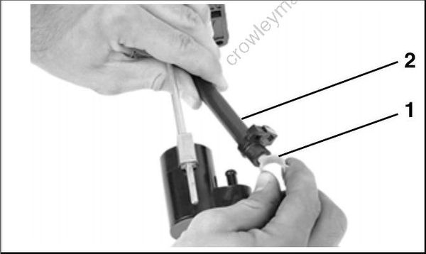
Use Plug/Holder, P/N 329661, and clamp to plug the pickup end of the hose.
12307
- Plug/holder
- Oil hose
Attach a vacuum tester to the outboard side of oil supply hose and draw 7 in. Hg (24 kPa) vacuum on the hose for at least five minutes. Repair or replace any leaking components. Reinstall the oil hose.
Check height of pickup assembly.
| Pickup Assembly Height | |
|---|---|
| 1.8 gallon tank | 6.84 to 6.96 in. (174 to 177 mm) |
| 3.0 gallon tank | 8.74 to 8.86 in. (222 to 225 mm) |

COB5657A
Height of Oil Pickup Assembly
Place a new seal on oil tank and reinstall pickup with filter into oil tank. Install and tighten screws.
Oil Injection Pump Function Test
Remove oil distribution hose from fitting at crankcase. Squeeze oil supply primer bulb to provide oil to injection pump.

005348
- Crankcase fitting
Running Test
Start the outboard and observe oil flow. Confirm that a small amount of oil is discharged while injection pump is activated.
Static Test
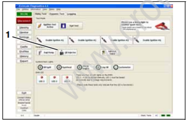
Use the Evinrude Diagnostics software oil injector test to activate injector. Confirm that a small amount of oil is discharged while injection pump is activated.
008116
Static Tests Screen
- Oil injector test button
Results:
• Oil flows from hose, compare to oil flow at other distribution hoses
• If one or more hoses fail to discharge oil, check for a kinked or restricted hose before replacing the oil injection pump assembly.
Oil Injection Fittings Flow Test
Make sure the oil injection fittings of the cylinder and crankcase assembly allow fluid to move.
Remove oil distribution hose from crankcase fitting. Temporarily install a length of oil hose on the fitting.
Use a Syringe, P/N 346936, filled with isopropyl alcohol to force fluid through hose and fitting.
LOW OIL Sending Unit Test
Remove oil from the oil tank
Turn the key switch ON. The dash mounted Engine Monitor system should show a LOW OIL warning.
Once the warning has been confirmed, refill the oil tank. The LOW OIL warning should stop when the oil level exceeds one-quarter of oil tank’s capacity.
