

EXPLODED DIAGRAM
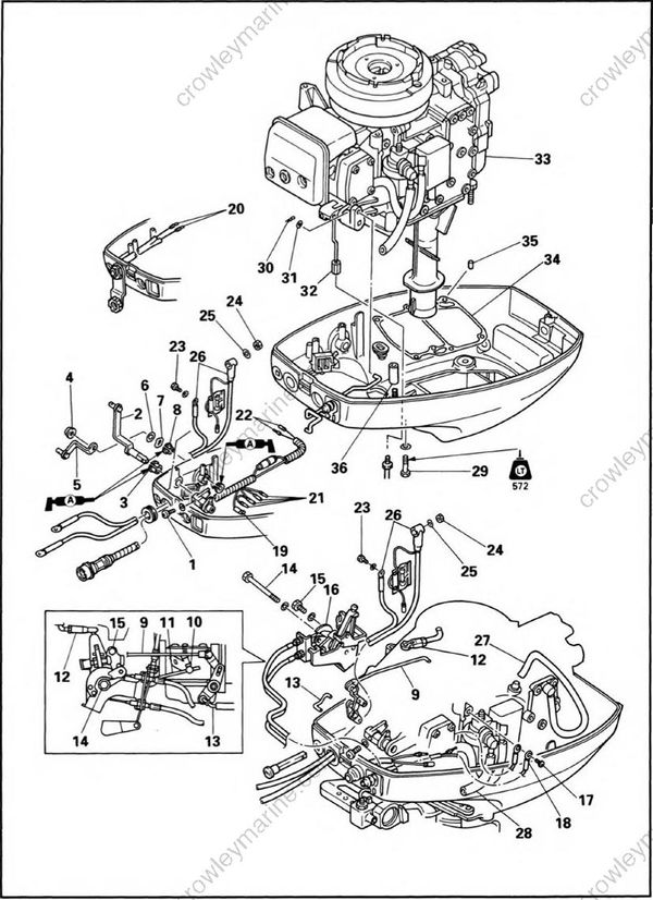
REMOVAL AND INSTALLATION CHART
| Step | Procedure/Part name | Q'ty | Service points |
|---|---|---|---|
| POWER UNIT REMOVAL | Follow the left "Step" for removal. | ||
| 1 | Screw (with washer) | 1 | for remote model |
| 2 | Shift lever link | 1 | |
| 3 | Bushing | 1 | |
| 4 | Nut | 1 | |
| 5 | Throttle lever link | 1 | |
| 6 | Plane washer | 1 | |
| 7 | Wave washer | 1 | |
| 8 | Bushing | 2 | |
| 9 | Choke link rod | 1 | |
| 10 | Screw | 1 | |
| 11 | Acceleration rod | 1 | |
| 12 | Link joint | 1 | |
| 13 | Choke knob rod | 1 | |
| 14 | Bolt (with washer) | 1 | |
| 15 | Bolt (with washer) | 1 | |
| 16 | Control pulley bracket assembly | 1 | |
| 17 | Bolt (with washer) | 1 | |
| 18 | Engine stop switch lead | 2 | Except for remote model |
| 19 | Wire harness ground lead | 1 | for remote model |
| 20 | 2P connector lead | 2 | for 2P connector model |
| 21 | Wire harness rectifier lead | 4 | for remote model |
| 22 | Wire harness starter relay lead | 2 | |
| 23 | Bolt (with washer) | 1 | Electrical starter model. |
| 24 | Nut | 1 | |
| 25 | Spring washer | 1 | |
| 26 | Battery cable | 1 | |
| 27 | Pilot water hose | 1 | |
| 28 | Fuel hose | 1 | |
| 29 | Bolt (with washer) | 6 | 8 x 30 mm |
| 30 | Clip | 1 | |
| 31 | Plane washer | 1 | |
| 32 | Shift lever rod | 1 | |
| 33 | Engine unit | 1 | |
| 34 | Upper case gasket | 1 | |
| 35 | Dowel pin | 2 | |
| 36 | Collar | 1 | |
| Reverse the removal steps for installation | |||
