

Checking the compression pressure
Start the engine, warm it up for 5 minutes, and then stop it.
Remove the clip from the engine shut-off switch.
Disconnect the fuel injector couplers and spark plug wires.
Remove all of the spark plugs, and then install the special service tool “1” into the spark plug hole.
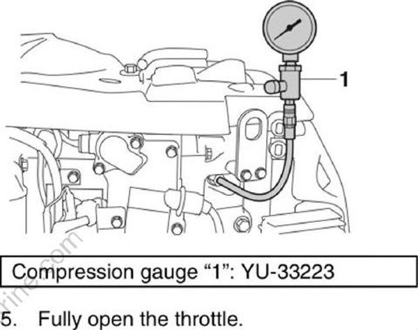
- Crank the engine until the reading on the compression gauge stabilizes, and then measure the compression pressure.
Minimum compression pressure (reference data):
880.0 kPa (8.80 kgf/cm2, 127.6 psi) @ 20 °C (68 °F)
Remove the special service tool.
Install all of the spark plugs, and then tighten the spark plugs to the specified torque.
Spark plug: 17 Nm (1.7 kgf-m, 12.5 ft-lb)
- Connect the spark plug wires and fuel injector couplers.
Checking the oil pressure
Disconnect the oil pressure switch lead from the oil pressure switch end.
Remove the oil pressure switch, and then install an oil pressure gauge “1” to the oil pressure switch installation hole.
Start the engine and warm it up until the engine idle speed stabilizes at 700-800 r/min.
Measure the oil pressure.
• Use a pressure gauge with an adapter that has a 1/8 pitch thread.
• The actual oil pressure may vary depending on the temperature and viscosity of the engine oil.
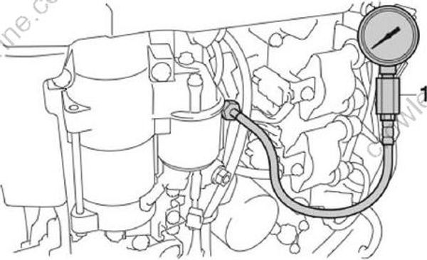
Oil pressure gauge “1”: (commercially available)
Oil pressure (reference data):
190.0 kPa (1.90 kgf/cm2, 27.6 psi)
@ 60 °C (140 °F) / SL 10W-30 engine oil / 750 r/min
450.0 kPa (4.50 kgf/cm2, 65.3 psi)
@ 61 °C (142 °F) / SL 10W-30 engine oil / 3000 r/min
Remove the oil pressure gauge “1”.
Install the oil pressure switch. See “Installing the oil pressure switch”
(7-58).
Checking the pulser coil air gap
Do not turn the flywheel magneto counter clockwise. Otherwise, the water pump impeller could be damaged.
Turn the flywheel magneto clockwise to align any protrusion “a” on the flywheel magneto with the protrusion “b” on the pulser coil.
Measure the pulser coil air gap “c”. Adjust if out of specification.
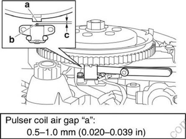
Adjusting the pulser coil air gap
- Loosen the pulser coil bolts “1”, and then adjust the pulser coil air gap.
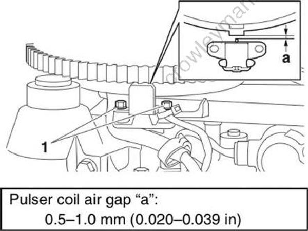
- Tighten the pulser coil bolts “1”, and then recheck the pulser coil air gap.
Checking the valve clearance
- Measure the valve clearances when the engine is cold.
- Cover the fuel components using a rag to prevent fuel from spilling out.
Do not turn the flywheel magneto counter clockwise. Otherwise, the water pump impeller could be damaged.
Remove all of the spark plugs.
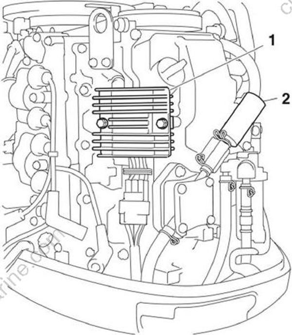
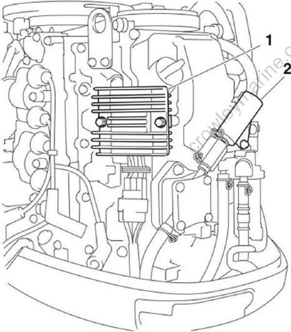
Remove the Rectifier/Regulator “1” and the holder “2”.
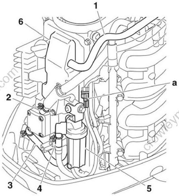
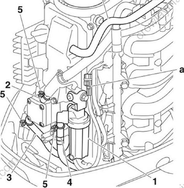
- Disconnect the water detection switch coupler “a”, blowby hose “1”, fuel hoses “2”, “3”, and “4”, and then remove the fuel filter assembly “5” and cylinder head cover “6”.
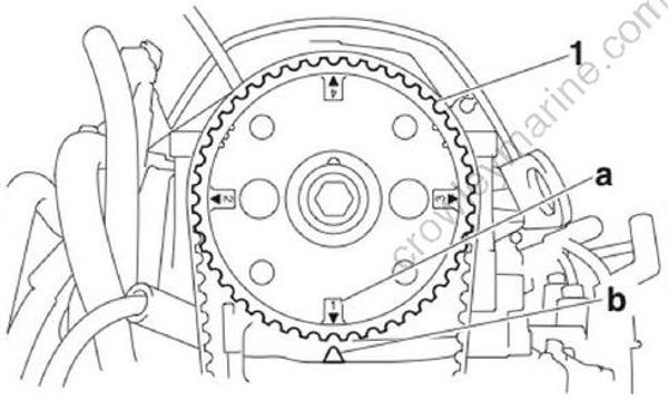
- Turn the flywheel magneto clockwise to align the “1▲” mark “a” on the driven sprocket “1” with the “△” mark “b” on the cylinder head.
- Measure the valve clearances “a” and “b” according to steps 6-8.
Write down the measurement data.
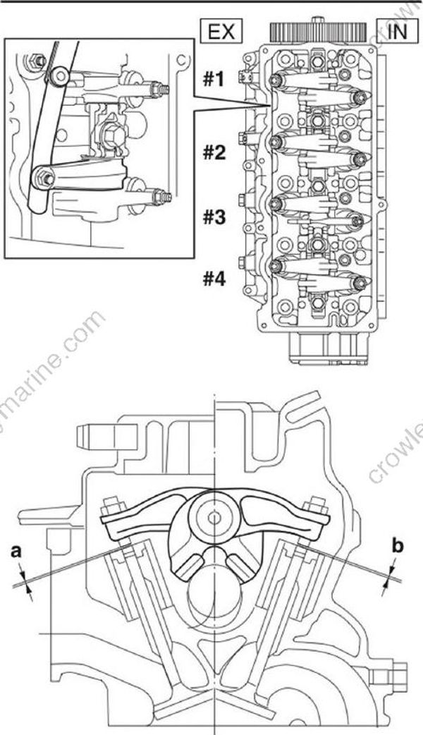
Valve clearance: Intake “a”: 0.15-0.25 mm (0.0059-0.0098 in)
Exhaust “b”: 0.25-0.35 mm (0.0098-0.0138 in)
- Measure the intake and exhaust valve clearances of the specified cylinders. Adjust if out of specification. #1
| #1 | #2 | #3 | #4 | |
| IN | ✓ | ✓ | — | — |
| EX | ✓ | — | ✓ | — |
—: Not applicable
✓ : Specified cylinder
- Turn the flywheel magneto clockwise 360° to align the “4▲” mark “a” on the driven sprocket “1” with the “△” mark “b” on the cylinder head.
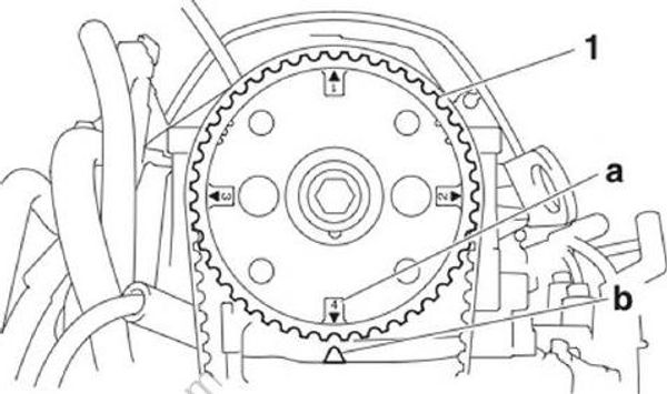
- Measure the intake and exhaust valve clearances of the applicable cylinders. Adjust if out of specification.
| #1 | #2 | #3 | #4 | |
| IN | — | — | ✓ | ✓ |
| EX | — | ✓ | — | ✓ |
—: Not applicable
✓: Specified cylinder
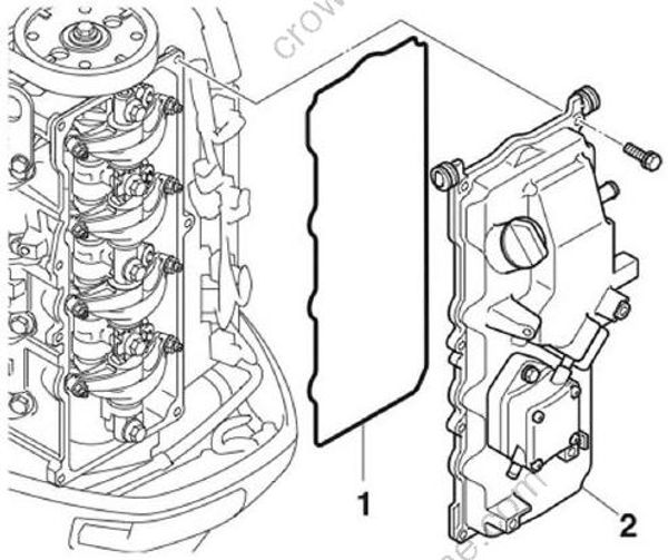
- Install a new gasket “1” and the cylinder head cover “2”.
Install the fuel filter assembly “1”, connect the fuel hoses “2”, “3”, and “4”, and then fasten the fuel hoses using the clamps “5”.
Install the water detection switch coupler “a”, and then connect it.
Connect the blowby hose “6”.
- Install the Rectifier/Regulator “1” and holder “2”.
Adjusting the valve clearance
Adjust the valve clearances when the engine is cold.
Do not turn the flywheel magneto counterclockwise. Otherwise, the water pump impeller could be damaged.
- Loosen the valve adjusting locknut “1”, and then turn the adjusting screw “2” until the valve clearance is within specification.
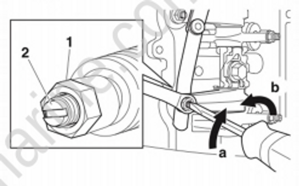
• To decrease the valve clearance, turn the adjusting screw “2” in direction “a”.
• To increase the valve clearance, turn the adjusting screw “2” in direction “b”.
- Tighten the valve adjusting locknut “1” to the specified torque, and then recheck the valve clearances.
Valve adjusting locknut “1”: 14 Nm (1.4 kgf-m, 10.3 ft-lb)
