

EXPLODED DIAGRAM (For ProV, S200 and 225 model)
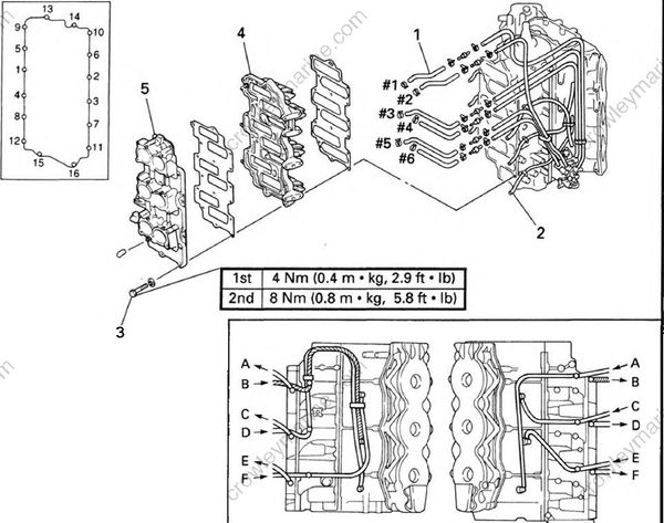
REMOVAL AND INSTALLATION CHART
| Step | Procedure/Part name | Q'ty | Service points |
|---|---|---|---|
| INTAKE MANIFOLD REMOVAL | Follow the left "Step" for removal. | ||
| Carburetor assembly | Refer to "CARBURETOR REMOVAL" section. | ||
| Oil tank assembly | Refer to "OIL TANK" section. | ||
| 1 | Oil hose | 6 | oil injection model |
| 2 | Drain less hose | 12 | |
| 3 | Bolt (with washer) | 16 | NOTE: Tighten the bolts in sequence and in two steps of torque. |
| 4 | Intake manifold assembly | 1 | |
| 5 | Intake manifold | 1 | |
| Reverse the removal steps for installation. |
EXPLODED DIAGRAM (Except for ProV, S200 and 225 model)
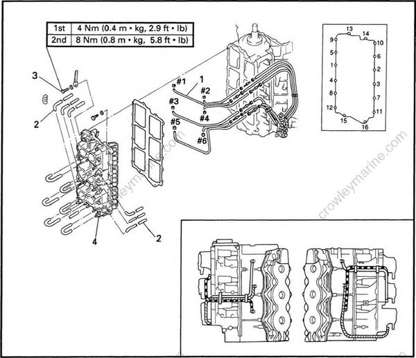
REMOVAL AND INSTALLATION CHART
| Step | Procedure/Part name | Q'ty | Service points |
|---|---|---|---|
| INTAKE MANIFOLD REMOVAL | Follow the left "Step" for removal. | ||
| Carburetor assembly | Refer to "CARBURETOR REMOVAL" section. | ||
| Oil tank assembly | Refer to "OIL TANK" section. | ||
| 1 | Oil hose | 6 | oil injection model |
| 2 | Drain less hose | 12 | |
| 3 | Bolt (with washer) | 16 | NOTE: Tighten the bolts in sequence and in two steps of torque. |
| 4 | Intake manifold assembly | 1 | |
| Reverse the removal steps for installation. |
