

EXPLODED DIAGRAM
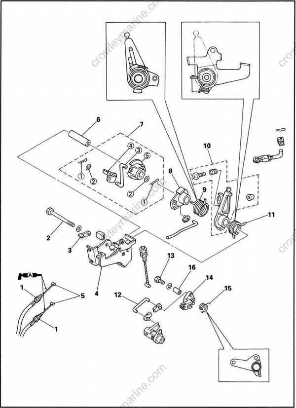
REMOVAL AND INSTALLATION CHART
| Step | Procedure/Part name | Q'ty | Service points |
|---|---|---|---|
| CONTROL UNIT DISASSEMBLY | Follow the left "Step" for removal | ||
| Control pully bracket assembly | Refer to the "POWER UNIT REMOVAL" section. | ||
| 1 | Throttle cable lock nut | 2 | |
| 2 | Bolt (with washer) | 1 | |
| 3 | Plate | 1 | for over revolution limit model |
| 4 | Control pully bracket | 1 | |
| 5 | Throttle cable | 2 | |
| 6 | Collar | 1 | |
| 7 | Control pully assembly | 1 | |
| 8 | Accelerator lever | 1 | |
| 9 | Accelerator lever spring | 1 | |
| 10 | Magneto control lever | 1 | |
| 11 | Magneto control lever spring | 1 | |
| 12 | Start-in-gear lever rod | 1 | |
| 13 | Bolt (with washer) | 1 | 6 x 20mm |
| 14 | Start-in-gear lever | 1 | |
| 15 | Start-in-gear lever spring | 1 | |
| 16 | Collar | 1 | |
| CONTROL PULLY DISASSEMBLY | |||
| (1) | Cotter pin | 2 | |
| (2) | Plane washer | 2 | |
| (3) | Control pully rod | 1 | |
| (4) | Control pully lever | 1 | |
| (5) | Control pully | 1 | |
| Reverse the removal steps for installation. |
