

Operation And Service Manual
If your jet drive is used in salt water, it would be best if all fasteners were removed and greased at least once every six months. Doing so will seal water out of the thread gaps and aid the prevention of corrosion. Failure to do this may result in the hardware being difficult, if not impossible, to remove at a later date.
STORAGE
Power Unit
Consult your Outboard Owner’s Manual for preparing the motor part of your jet drive for storage.
Jet Unit
Grease the drive shaft bearing by pumping in enough extra grease to purge any moisture. Additionally, re move and refit the jet drive impeller, greasing the bore, key, and plastic sleeve. In addition, clean and grease all hardware.
ADJUSTMENTS
Shift Cam Assembly with Neutral Adjustment
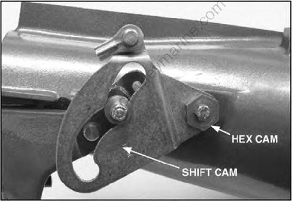
A shift mechanism comprised of a shift cam with an adjustable pivot point has been incorporated. When the pivot point is properly located by the hex cam eccentric, in the neutral position, the forward thrust of the jet-driven outboard will be negligible.
Neutral Adjustment of All Models
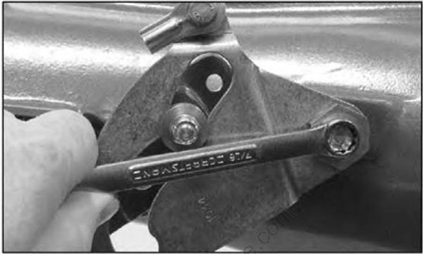
- Loosen the inner pivot bolt securing the Hex Cam.

- Using light pressure against the gate, move it upward toward reverse until the cam roller is nested in the neutral detent in the forward side of the cam slot. (During operation jet pressure will push the gate toward reverse and cause the roller to maintain contact with the front edge of the cam.)
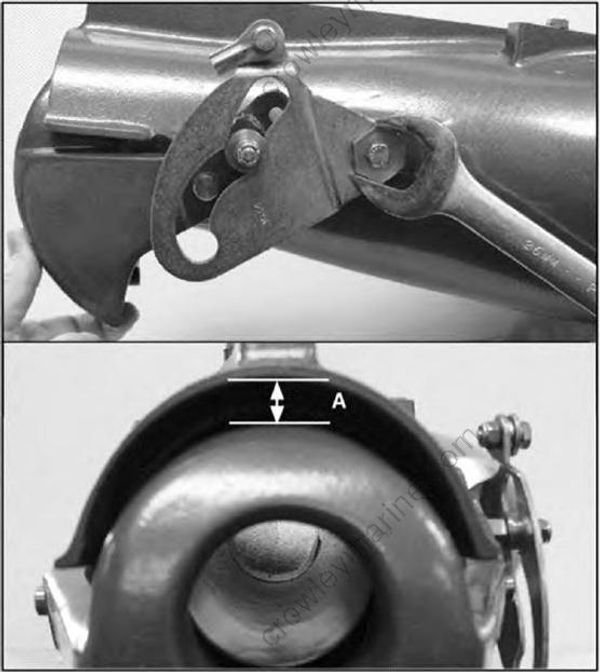
- Hold the gate in this position while rotating the Hex Cam either direction until the gate clears the underside of the nozzle hood by measurement (A). This measurement should be 15/32 for pumps with a 2-1/2" O.D. exhaust pipe and 9/16 for those with 2" O.D exhaust pipes
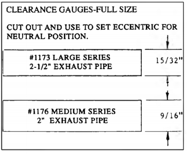
(Hint: Photocopy this page and cut out the appropriate gauge above and temporarily glue it to the housing using a glue stick, see illustration above):

The hex cam should be adjusted so that the widest point as measured (from the center of the inner pivot bolt to the outside of the hex cam) faces upward between the 9 and 3 O’clock positions.
Adjust the shift cable ends and the cable anchor bracket on the jet drive so the roller is in the neutral nest when the shift handle is in neutral. Tighten both the cable and nuts.
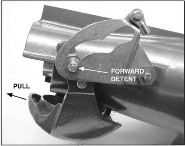
- Shift to forward. The roller should be at the end of the slot securely in the detent of the cam so the gate cannot be forcibly rotated toward reverse. Pull on the gate by hand to verify this. If the for ward lock condition is not met, readjust the cable positions, giving less importance to the roller position in neutral.
Do not be concerned if, after proper linkage and cable adjustments, the reverse gate does not fully close over the nozzle when the shifter selects reverse; water pressure will close it all the way during normal operation in the water.
If the neutral detent position is out of adjustment, extra loading of the shift cable will result. Some con trolbox styles may not shift from neutral easily if this situation is encountered.
If not properly adjusted, the reverse gate can be engaged by forward motion of the boat. This will cause the engine to kick up and out of the water, similar to hitting a submerged object in a propeller-driven craft.
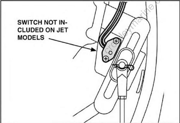
EFI four strokes (equipped with a propeller) use a shift position switch to monitor for neutral selection. The switch circuit is closed in neutral and opens in forward and reverse. RPM is limited if the switch is closed to prevent over-revolution. Outboards built specifically for use with a jet pump and have a “J” in their model name do not have this switch installed during assembly. However, the engine harness does have a blank socket for the switch but it has a water tight cover (P/N: 68V-82582-10-00) installed to protect the harness from the elements.
It is normal for a jet drive outboard to continuously record a shift switch code (28) due to the switch being absent from the shift linkage. Normal operation is not interrupted and the operator is unaware of the diagnostic code unless the engine is paired with a Command Link® Tachometer (see Command Link® Compatibility, page 32).
Steering Trim
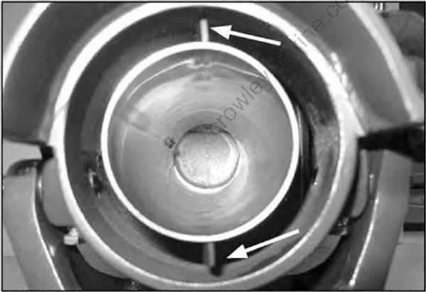
The outer surface of the exhaust tube inside the jet nozzle has two vertical tabs on the top and under side for directing the water jet slightly to starboard. The diversion is engineered to trim the unit countering for the minute steering torque created by the impeller. Some applications may tend to pull more than others. If this is the case, it is permissible to bend the tabs to fine tune the steering trim for the specific application.
PERFORMANCE TIPS
Here are some pointers for obtaining maximum performance from Jet Drive outboards:
Keep the leading edges of the impeller sharp.Edges that have been blunted by gravel beyond 1/32" tend to break up the water. This results in slippage and excessive engine RPM.
Keep the grille bars parallel to prevent large rocks or other debris from entering the impeller, causing damage or possibly lodging in the nozzle.
Select as light a hull as possible for the intended use.
Keep the boat bottom smooth and free of dents. This will reduce drag and air entrapment.
The optimum bottom width is 48 to 60 inches. Beyond 60", the boat rides so high that air is allowed to enter the pump. This is likely in choppy water particularly when running with the wind. Less than 48", on the other hand, can make it difficult to reach a plane with a heavy load.
A slight vee in the boat bottom gives better steer ing and helps to keep solid water in the pump. A 3" drop at centerline on a 60" bottom is enough. Beyond that, shallow draft is sacrificed.
The power trim is useful to bring a heavy load on plane. Tipping the engine under points the jet stream down, which helps lift the stern. After reaching a plane, trim the engine out until the jet stream is horizontal (the engine drive shaft is vertical).
Power trim is also useful when running slowly in shallow water, such as when backing off the beach. In these conditions, the engine can be tilted back 15° to 20°, reducing the tendency to pick up gravel. Keep your eye on the cooling water pilot hole to make sure the engine is getting water.
When on plane, do not trim the engine out beyond horizontal, so the jet stream points up into the air or the bow lifts. This will reduce the ram angle on the water intake and will cause severe cavitation burns on the impeller blades
- A four blade stainless steel impeller is standard with the F150 and is available for other models as well. Stainless impellers provide superior performance and can extend service life in areas where avoiding gravel intake is difficult or impossible. If you have trouble locating these impellers in the market, contact your Yamaha Outboard Dealer. Stailess impellers are not available from Yamaha.

- Some larger displacement jet drives can experience a loss of performance above 4500 rpms. Symptoms include an increased level of noise without any increase in thrust, when advancing the throttle. Inspect the leading edge of impeller liner looking up through the intake grates. If the liner protrudes beyond the surface of the foot casting, it may be causing cavitiation. Grinding down the protruding material will allow undisturbed water flow and correct this condition.
