
OMC Stringer Nominal Neutral Adjustment
Duración de la reparación: 30 to 60 mins
Dificultad de la reparación: Medium
added
updated

OMC Stringer Nominal Neutral Adjustment
BRP Marine
I/O
The following adjustment procedure centers the clutch dog midway between forward and reverse gear, and must be done if shift system components have been changed due to servicing or vertical drive serial number does not match number on converter housing.
Disconnect remote control shift cable if attached or remove the plastic alignment fixture if still installed.
Apply the special graduated decal supplied in Propeller Parts Kit over the existing decal on the cover. Align decal with outer radius (both ends) of existing decal See Figure 7-1-93. Proceed with neutral adjustment with boat running either in slip or dock or out of water using an external water supply.

Figure 7-1-93
When using an OMC Flushing Adapter Kit, remove the propeller before using to prevent accidental contact with a moving propeller.
Always turn water on before starting engine and control water pressure Full water pressure may cause damage to engine. Water should flow from exhaust relief on bottom of intermediate housing or from exhaust outlet on propeller.
- Start engine, run at idle, and manually move the shift arm on shift converter housing to full reverse position. Slowly move the arm in the opposite direction until the unit comes out of gear. Use the shift arm arrow as a guide, and mark this position on the decal. See Figure 7-1-94.
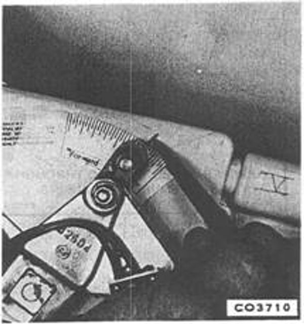
Figure 7-1-94
- Move the shift arm to full forward position. Slowly move the arm in opposite direction until the unit comes out of gear. Mark this position on the decal. See Figure 7-1-95.

Figure 7-1-95
- Using the graduations on the decal between the two "out-of-gear" marks from Steps 3 and 4, mark the mid-point or "Nominal Neutral" position between these two marks. This is the correct nominal neutral position. See Figure 7-1-96. The distance between the two out-of-gear marks must be a minimum of 19/32" (1/2" measured at shift arm pin). This is the minimum neutral range. See Figure 7-1-96. Repeat this procedure to verify neutral position and minimum neutral range. If the neutral range is less than the minimum the shift system must be inspected to find the cause.
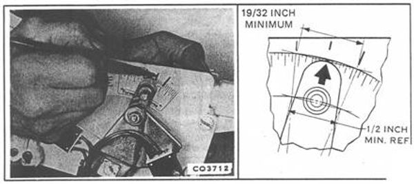
Figure 7-1-96
Continued use of a shift system with less than 1 9/32 inch neutral range (1/2 inch at shift arm pin) may allow unit to start in gear, causing operator to lose control of boat.
- Whenever nominal neutral is reset, it must be followed by a readjustment of the overstroke switch.
Next Step: OMC Stringer Overstroke Switch Adjustment