

Lifting Fixtures
To avoid personal injury, make sure the lifting capacity of the hoist is at least twice the weight of the outboard.
DO NOT allow the lift hook or chain from the hoist to come in contact with any part of the engine during lifting.
Remove shipping carton.
Use correct Lifting Fixture to lift outboard:
| Model | Lifting Fixture |
|---|---|
| 90° V6 | P/N 396748 with 1 3/4 in. screws |
| 60° V4–V6 | P/N 342672 |
| 40–90 HP | P/N 396748 with 1 1/8 in. screws |
| 15–30 HP | P/N 354717 |
90° V6 MODELS
Position lifting tool on flywheel and seat the three screws completely
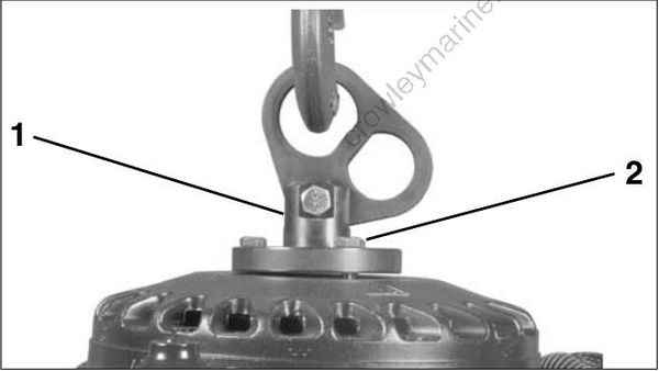
002419
- Lifting fixture
- 1 3/4 in. screws
Fasten appropriate chain hook to eye of tool. Carefully hoist outboard with chain and unbolt outboard mounting brackets from frame.
60° V4 AND V6 MODELS
Position lifting tool on crankshaft and tighten the center retaining screw securely using a 1/4 in. Allen wrench.
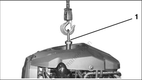
004945
- Center retaining screw
Fasten appropriate chain hook to eye of tool. Carefully hoist outboard with chain and unbolt outboard mounting brackets from frame.
40–90 HP MODELS
With recoil starter removed, place lifting tool on flywheel and seat the three screws completely. Refer to RECOIL STARTER REMOVAL in the correct Service Manual.
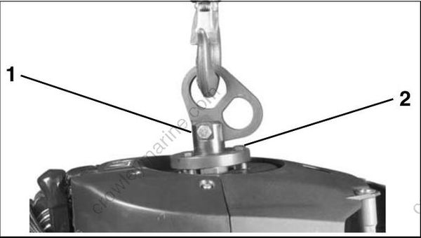
002098
- Lifting fixture
- 1 1/8 in. screws
Use only the 1 1/8 in. (short) screws, P/N 398067, included with the tool to avoid damage to electronic components under the flywheel.
Fasten appropriate chain hook to eye of tool. Carefully hoist outboard with chain and unbolt outboard mounting brackets from frame.
15–30 HP MODELS
Install Lifting Tool, P/N 354717, on both sides of the tilt tube.
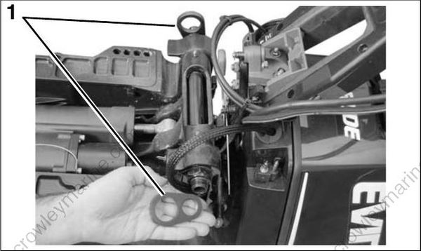
007122
- Lifting tool, P/N 354717
To avoid personal injury or outboard damage, be sure the lifting tool is fully threaded on both sides of the tilt tube.
Use an appropriate chain, at least 36 inches (91 cm) long with two snap hooks, each capable of lifting 500 lbs. (227 kg).
Attach hooks to lifting device and attach chain to hoist.
Use this tool for horizontal lifting of 30 HP and smaller Evinrude E-TEC models ONLY.
DO NOT use this tool to lift outboards larger than 30 HP Evinrude E-TEC models.
To avoid personal injury and boat or outboard damage, DO NOT use this tool to install or remove outboard from transom as outboard can unexpectedly tip.
Lift the engine out of the carton.

007123
- Lifting tool, P/N 354717
Remove upper motor cover.
Place clean pad or cardboard on the floor.
Lower outboard onto the pad. Use hoist to carefully roll the outboard onto its port side.
To avoid damage to the outboard, DO NOT allow the outboard to fall unrestrained.
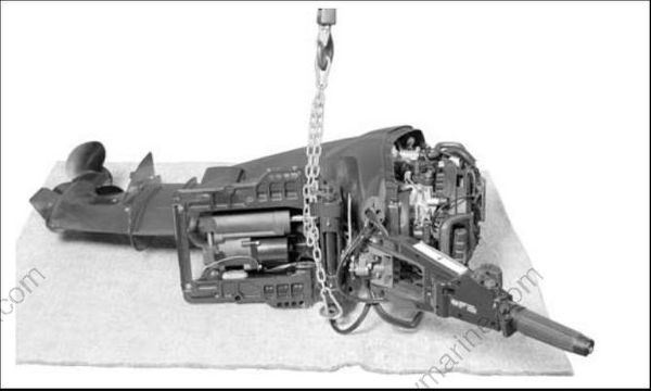
007211
Remove chain from lifting tool.
Remove lifting tool from outboard.
Attach chain to lift eye on back of engine block.
If the chain snap hooks are too large, the cast in lift eye could break causing the outboard to drop suddenly causing personal injury and damaging the outboard.
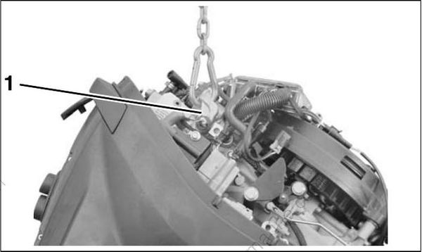
007212
- Lift eye
Carefully lift engine with hoist.
To avoid damage to the outboard, lift the outboard in one smooth motion. DO NOT allow the outboard to bounce.
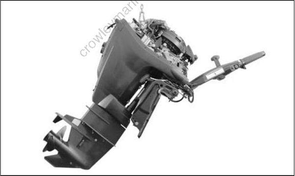
007213
Steering System
Mechanical Cables
All Evinrude outboards equipped with tilt tubes are compatible with mechanical steering systems that meet ABYC Standard P-17. Single-cable mechanical steering systems can be used on single or dual-outboard installations if an ABYC-approved steering link is used.
Dual-cable mechanical steering helps provide firm steering control at high speeds.
Extend the steering cable and lubricate the inner core before installation.
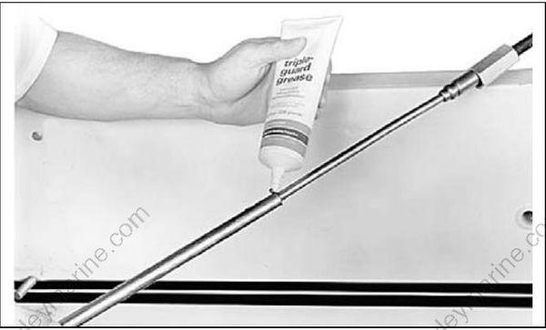
5873
ABYC-approved mechanical steering cable.
IMPORTANT: Install steering cable through tilt tube before mounting outboard on transom. Tighten nut securely.
DO NOT use cable over pulley steering on 40 HP and larger outboards.
