

Engine Monitor System
All remote controlled outboards must be equipped with an engine monitoring system to warn the operator of conditions that could damage the outboard.
The engine monitor system includes sensors on the outboard and oil tank, a warning horn, a dashmounted display, and related wiring.
The outboard’s EMM sends information about monitored functions to:
• SystemCheck gauges, or
• An I-Command or ICON display.
IMPORTANT: Operating the outboard without an engine monitor will void the warranty for failures related to monitored functions.

007988
SystemCheck Gauges
SystemCheck gauges are used with mechanical remote control systems only.
SystemCheck gauges receive monitored information from the outboard through a Modular Wiring System (MWS) harness.
Refer to SystemCheck (MWS) Harness Connections on p. 12.
I-Command Displays
I-Command digital displays are designed specifically for NMEA 2000 certified Evinrude E-TEC outboards. These displays provide enhanced engine and boat performance information. Multiple functions are integrated into the easy-to-use displays. Additional displays and accessories can be added with the plug and play design.
I-Command information displays can be used with either a mechanical remote control system or with an Evinrude ICON system. For complete installation instructions, refer to I-Command Installation Guide.
When installing an I-Command network, remember:
• A terminator must be installed at each end of the network
• There should be no open or unused network device connectors
• The network should be grounded at a single location only
• A maximum of 50 devices can be attached to the network *
• The distance between any two points on the network must not exceed 100 meters (328 ft.).
The EMM on Evinrude E-TEC outboards has a load equivalency number of 1. Less than 50 mA of the network’s power is used by the EMM.
If a mechanical control is used, the I-Command network receives monitored information through an I-Command network harness connected directly to the outboard’s EMM. An I-Command Ignition and Trim harness is required to carry start, stop, and trim signals to the outboard.
Refer to I-Command Harness Connections With Mechanical Remote Control on p. 13.
If an ICON control is used, the I-Command network receives monitored information through the ICON control network gateway.
Refer to Evinrude ICON / I-Command Harness Connections on p. 14.
SystemCheck (MWS) Harness Connections

007989
Typical MWS wiring with a side-mount mechanical remote control
- 6-Pin Connector – Connect to a pre-wired remote control or to a dash-mounted key switch.
- 3-Pin Connector – Connect to remote control trim switch or to a dash-mounted trim switch.
- Black, purple, white/tan wires – Connect to the trim gauge.
- Black, purple, gray wires – Connect to a conventional tachometer when a SystemCheck tachometer is not used.
- 2-Pin Connector – Must connect to the warning horn in all installations.
- 8-Pin Connector – Connect to a SystemCheck gauge or tachometer.
I-Command Harness Connections With Mechanical Remote Control
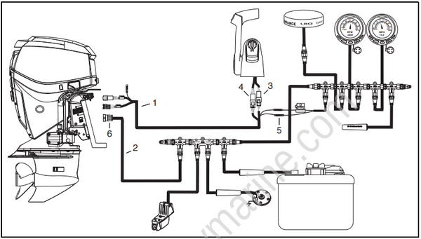
007990
Typical I-Command wiring with a binnacle-mount mechanical remote control
- I-Command Ignition and Trim Harness
- I-Command Network Harness
- 6-Pin Connector – Connect to a pre-wired remote control or to a dash-mounted key switch.
- 3-Pin Connector – Connect to remote control trim switch or to a dash-mounted trim switch.
- Purple, black wires – Connect to network power supply.
- 4-Pin Amp Connector – Connect to outboard EMM.
Evinrude ICON / I-Command Harness Connections
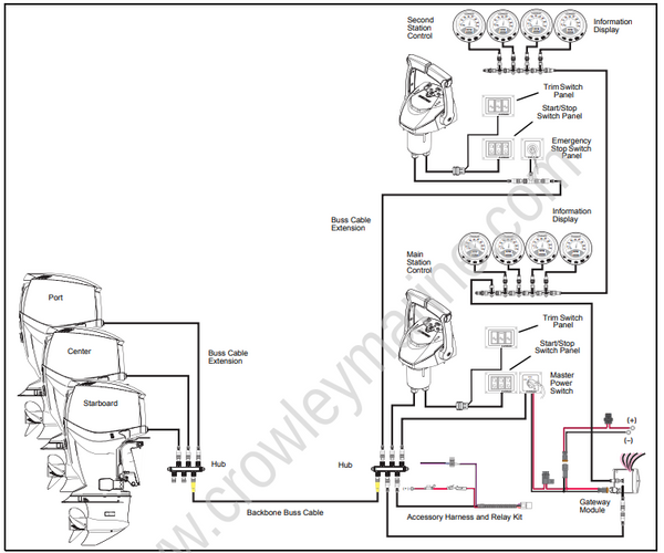
007978
Typical Evinrude ICON network for three outboards and two control stations
