

EXPLODED DIAGRAM
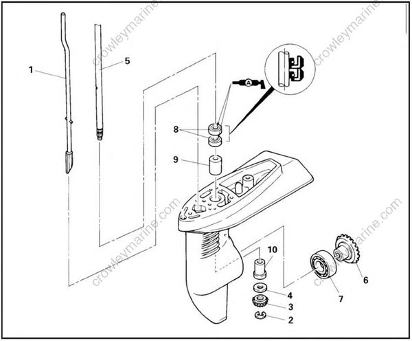
REMOVAL AND INSTALLATION CHART
| Step | Procedure/Part name | Q'ty | Service points |
|---|---|---|---|
| DRIVE SHAFT, FORWARD GEAR AND SHAFT ROD REMOVAL | Follow the left "Step" for removal. | ||
| Propeller shaft ass'y | |||
| Water pump ass'y | |||
| Plate (water pump) | |||
| 1 | Shift rod | 1 | |
| 2 | Circlip (pinion gear) | 1 | |
| 3 | Pinion gear | 1 | NOTE:When removing the pinion gear, pull up the drive shaft slight. |
EXPLODED DIAGRAM
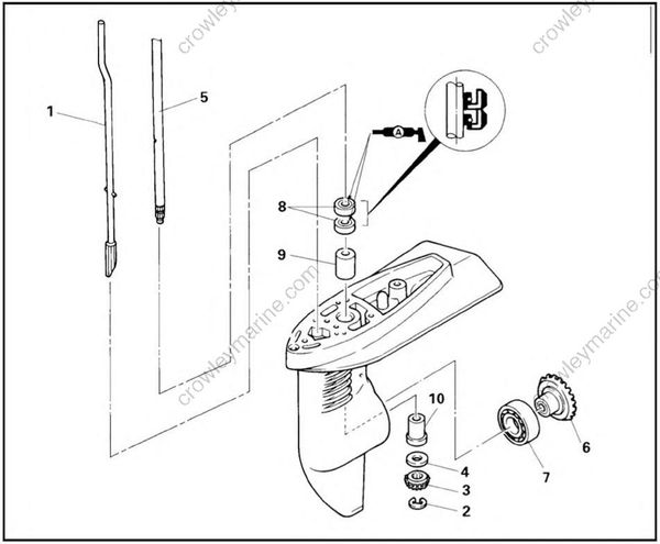
| Step | Procedure/Part name | Q'ty | Service points |
|---|---|---|---|
| 4 | Plate washer | 1 | |
| 5 | Drive shaft | 1 | |
| 6 | Forward gear | 1 | |
| 7 | Ball bearing (forward gear) | 1 | |
| 8 | Oil seal (drive shaft) | 2 | Not reusable |
| 9 | Upper bushing | 1 | |
| 10 | Lower bushing | 1 | |
| Reverse the removal steps for installation. |
SERVICE POINTS
Pinion and forward gear removal
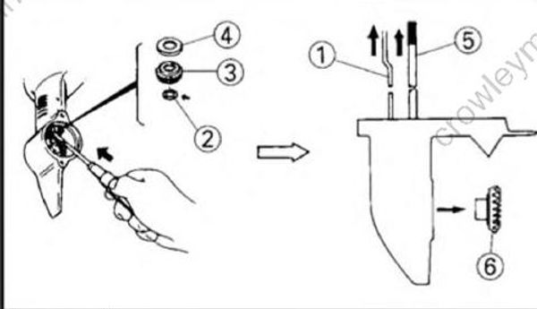
- Remove:
- Shift rod (1)
- Circlip (2)
- Pinion gear (3)
- Plate washer (4)
- Drive shaft (5)
- Forward gear(6)
When removing the pinion gear, pull up the drive shaft slightly.
Lower case disassembly
- Remove:
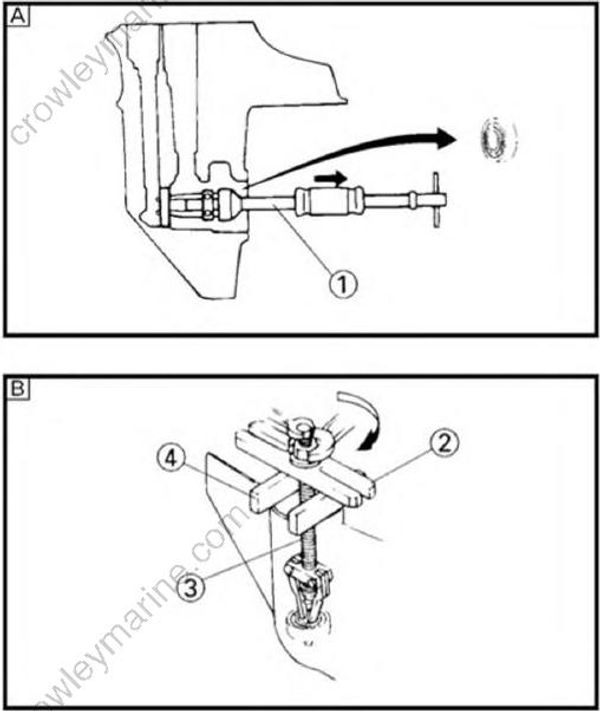
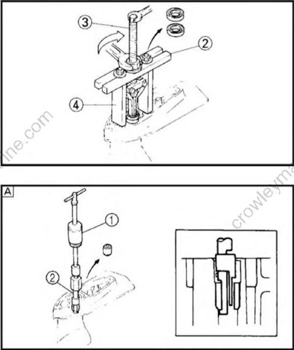
- Ball bearing (forward gear)
Install the bearing puller in the forward gear bearing, and tighten the puller so that claws hold the inner race of the bearing; see the illustration. Remove the bearing with the bearing puller.
Slide hammer set (1): YB-06096
Stopper guide plate (2): 90890-06501
Bearing puller(3): 90890-06535
Stopper guide stand (4): 90890-06538
[A] For USA and CANADA
[B] Except for USA and CANADA
- Remove:
- Oil seals (1)
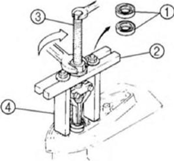
Install the puller attachment and puller in the drive shaft oil seals, tighten the puller so that claws hold the oil seals and remove the seals with the puller.
Stopper guide plate(2): 90890-06501
Bearing puller (3): 90890-06535
Stopper guide stand (4): 90890-06538
- Remove:
- Upper bushing
As shown, install the bushing puller in the upper bushing, and insert the puller so that claw hold the underside of the bushing. Remove the bushing with the bushing puller.
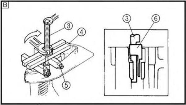
Slide hammer set (1): YB-06096
Bushing puller: YB-06178 (2) 90890-06646 (3)
Stopper guide plate (4): 90890-06501
Stopper guide stand (5): 90890-06538
Bushing puller spacer(6): 90890-06648
[A]For USA and CANADA
[B] Except for USA and CANADA
- Remove:
- Lower bushing
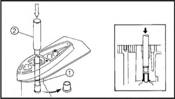
Install the bushing remover attachment and driver rod in the drive shaft lower bushing, and remove the bushing with the driver rod.
Bushing attachment (1): YB-06027/90890-06651
Driver rod (2): YB-06229/90890-06652
Pinion and forward gear inspection
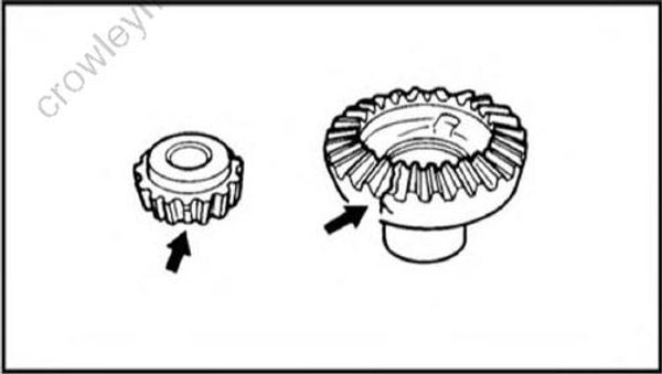
- Inspect:
- Tooth
- Dog
Wear/damage -> Replace.
Drive shaft inspection
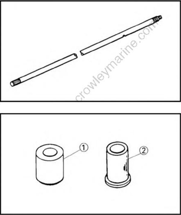
- Inspect:
- Drive shaft
Wear/damage -> Replace.
Bushing inspection
- Inspect:
- Upper bushing (1)
- Lower bushing (2)
Wear/crack/damage -> Replace.
Shift cam inspection
- Inspect:
- Shift cam
Wear/damage -> Replace.
Bearing inspection
- Inspect:
- Bearing
Pitting/rumbling -> Replace.
Lower case inspection
- Clean:
- Lower case
Use a soft brush and solvent.
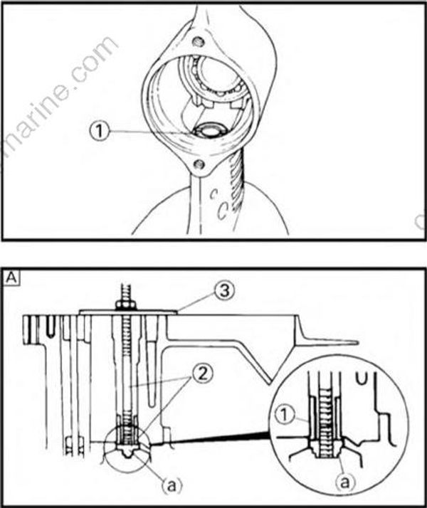
- Inspect:
- Water passage
Mineral deposits/corrosion -> Clean.
- Inspect:
- Lowercase
Crack/damage -> Replace.
Lower case assembly
- Install:
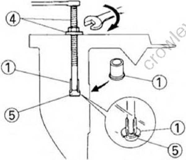
- Lower bushing (1)
● Using the special tools press-fit bushing until it contacts the gear case.
● (For US and CANADA) In this operation, the bushing support (a) of the bushing installer ass'y (2) should be installed with the larger diameter end on the bushing side.
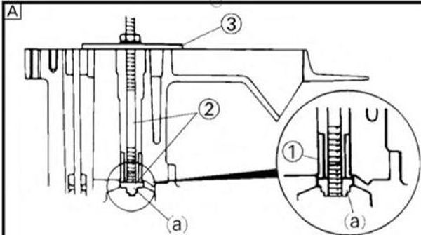
Bushing installer ass'y (2): YB-06029
Needle bearing installer (3): YB-06169
Bushing installer center bolt (4): 90890-06601
Bushing attachment (5): 90890-06649
[A] For USA and CANADA
[B] Except for USA and CANADA
- Install:
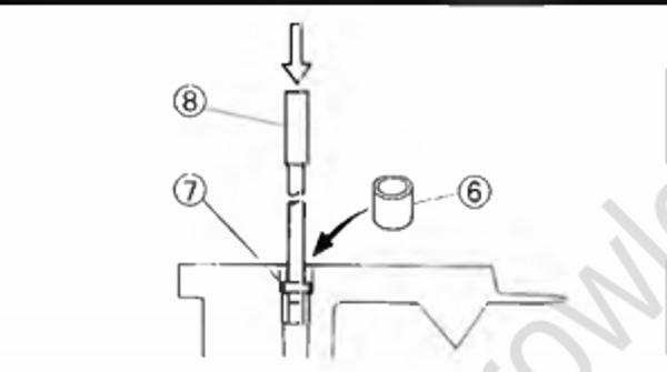
- Upper bushing
Bushing attachment (7): YB-06027/90890-06651
Driver rod (8): YB-06229/90890-06652
- Install:
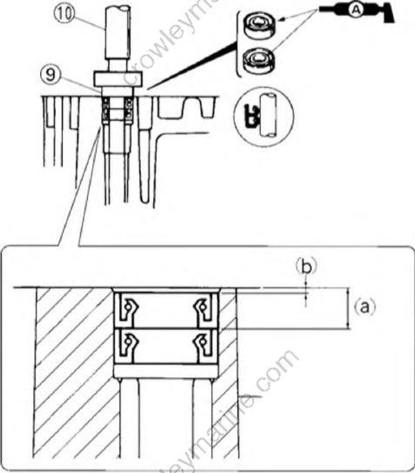
- Oil seal
Bearing attachment (9): YB-06082/90890-06615
Driver rod (10): YB-06229/90890-06604
Use the oil seal installer (bearing attachment), install the two oil seals at the specified depth from top of the lower case mating surface (one by one).
Oil seal set depth:
(a): 8.0 mm (0.3 in)
(b):1.0 mm (0.04 in)
- Install:
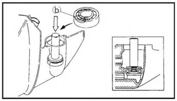
- Ball bearing (forward gear)
Install the ball bearing with its manufacturer's marks (b) facing the forward gear.
Bearing installer: (Ball bearing attachment) YB-06016/90890-06634
Driver rod: YB-06071/90890-06606
