

EXPLODED DIAGRAM
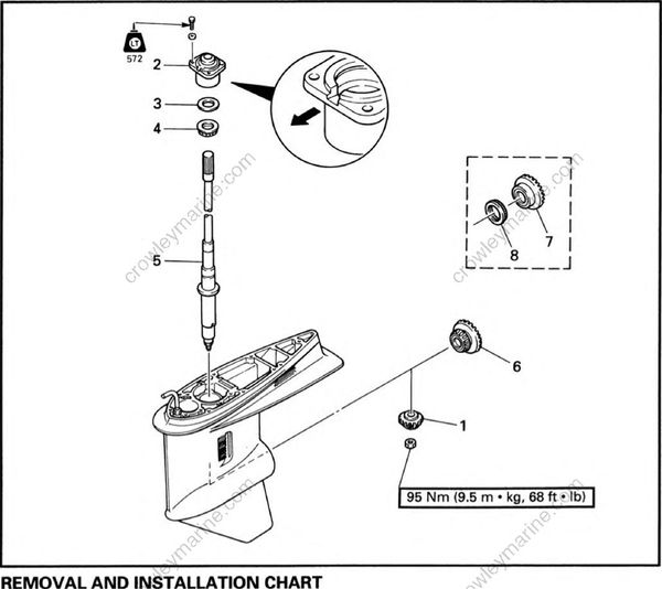
REMOVAL AND INSTALLATION CHART
| Step | Procedure/Part name | Q'ty | Service points |
|---|---|---|---|
| DRIVE SHAFT REMOVAL | Follow the left "Step" for removal | ||
| Propeller shaft housing | Refer to "PROPELLER SHAFT HOUSING REMOVAL" section. | ||
| 1 | Pinion gear | 1 | |
| 2 | Drive shaft housing | 1 | |
| 3 | Pinion gear shim | • | |
| 4 | Thrust bearing | 1 | |
| 5 | Drive shaft | 1 | |
| 6 | Forward gear assembly | 1 | |
| 7 | Reverse gear assembly | 1 | Counterrotation model |
| 8 | Thrust bearing | 1 | |
| Reverse the removal steps for installation |
•: As required
SERVICE POINTS
Drive shaft removal and installation
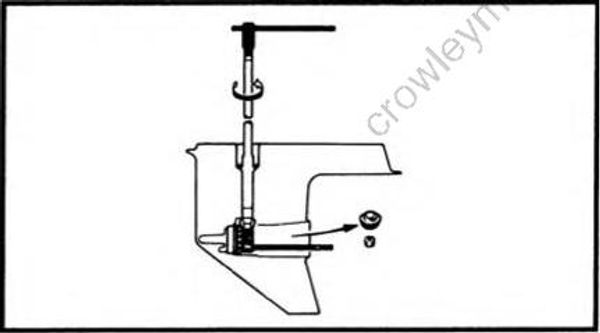
- Loosen and tighten:
• Pinion nut
Drive shaft holder: YB-06201/90890-06520
Pinion nut holder: 90890-06505
Pinion gear inspection
- Inspect:
• Tooth
• Dog
Wear/Damage -> Replace.
Drive shaft inspection
- Inspect:
• Drive shaft
Wear/Damage->Replace.
EXPLODED DIAGRAM
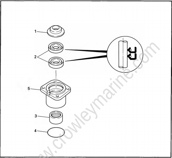
REMOVAL AND INSTALLATION CHART
| Step | Procedure/Part name | Q'ty | Service points |
|---|---|---|---|
| DRIVE SHAFT HOUSING DISASSEMBLY | Follow the left "Step" for removal. | ||
| Drive shaft | Refer to "DRIVE SHAFT REMOVAL" section. | ||
| 1 | Oil seal cover | 1 | |
| 2 | Oil seal | 2 | |
| 3 | Needle bearing | 1 | |
| 4 | O-ring | 1 | |
| 5 | Drive shaft housing | 1 | |
| Reverse the removal steps for installation. |
SERVICE POINTS
Drive shaft housing disassembly
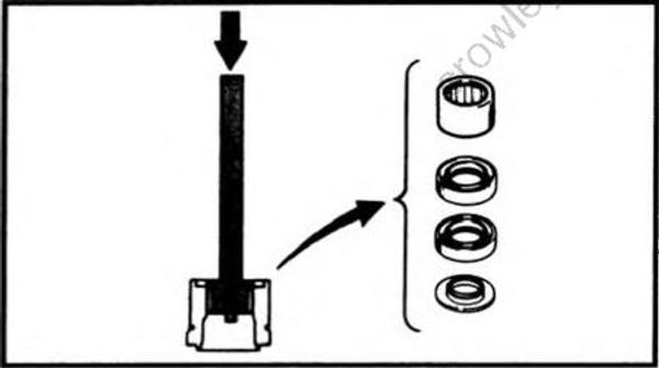
- Remove:
• Needle bearing
Needle bearing attachment: YB-06196/90890-06610
Driver rod: YB-06071 /90890-06606
Drive shaft housing inspection
- Inspect:
• Drive shaft housing
Crack/Damage -> Replace.
Drive shaft housing assembly
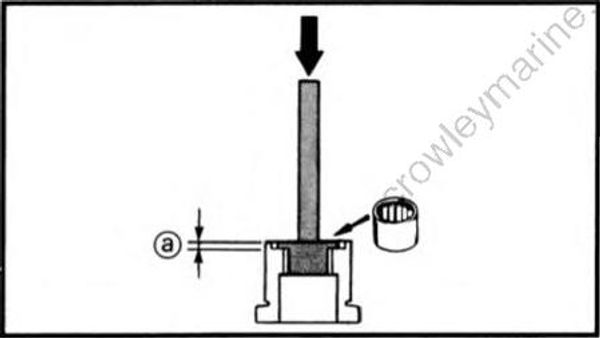
- Install:
• Needle bearing
Position (a): 5.75 ~ 6.25 mm (0.226 ~ 0.246 in)
Needle bearing attachment: YB-06196/90890-06610
Driver rod: YB-06071/90890-06604
Bearing depth plate: 90890-066032.
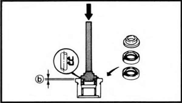
- Install:
• Oil seal
Position (b): 0.25 ~ 0.75 mm (0.010 ~ 0.030 in)
Needle bearing attachment: YB-06195/90890-06633
Driver rod: YB-06071 /90890-06606
